
 JAMES HICKMAN looks at how to run the Gaugemaster Shuttle Unit on a DCC layout.
For some people the thought of converting a layout to DCC Control can be a daunting project. So many things to convert and so many new things to learn! The more you read, the more daunting it may become, but it need not be. In previous articles we have shown you digital controllers, and how to operate points and accessories via digital command control, but what about the other elements that are left behind? Analogue controllers become brilliant controllable power supplies for non-digitally controlled devices such as street lighting or action scenes. Transformers are still needed and many accessories can be powered off these as well, but what about your shuttle units? In this article I will how to look at integrating your analogue shuttle module onto a DCC layout, with the addition of a few easy to install components.

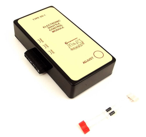
The Gaugemaster GMC-SS1 Shuttle unit is a device that allows a locomotive to shuttle between positions on a layout automatically, using brakes in the rail bridged by diodes. The unit then changes the polarity and sends the locomotive in the reverse direction, repeating this until turned off.
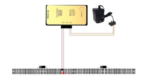
When using the unit on an analogue layout the unit is wired in as below:
Click image for a larger version.
The diagram is from Martin Lovell's article, "Gaugemaster Super Shuttle and Station Stop". If you have not read his article, or have not installed your unit yet, I would recommend reading Martin's article before reading on.
There are two ways. The first would be to have the shuttle set up as described alongside your digital track. This could then be a nice addition of movement to your layout. The downside is this section would still need to be controlled by an analogue controller. The second way allows you to keep the same design of running the shuttle alongside the track, but with one main difference; the shuttle is controlled from your digital controller.
It's actually relatively simple. All you need is a decoder (I would recommend an 8 Pin Direct Plug Decoder for simplicity) and a DCC71 Prodigy Adapter Plate.
The first step is to disconnect the analogue controller. This will free up the 12v DC input for the Shuttle unit. The 16v AC is still connected, powering the unit, or if you are currently powering it from the 16v AC power outlet from your controller, switch to a separate transformer to relieve the controller. Now simply put the controller to one side, ready for powering your lighting/accessories at a later date.
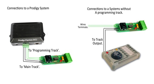
Your connections will now look like this:

From here, the first thing to do is to add the DCC71 Adapter Plate. This little device allows the control of an analogue locomotive on a section of separate track by means of an additional decoder. (Craig explains this well in his article, "Gaugemaster DCC DC Adaptor Plate/Decoder Tester"). The DCC71 comes with four wires attached at one end to a Prodigy plug, and a socket at the other end. Stage 1 is to unscrew the wires from the green plug, and insert the plug into the opposite end. This will leave you with four wires hanging free. These attach to your DCC controller. The two black wires go to the Main Track output of your prodigy, and the two green wires attach to the Programming Track output. If you don't have a separate programming track, simply isolate the two green wires and simply do not use them. You should now have the following:

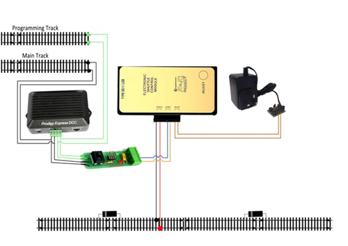
You now have four terminals on the other end not being used, until now. Stage 2 is to connect those in line with the black cables (the lower two in the image above, to the 12v DC input of the Shuttle unit marked 'Cont'. You should now have the following circuit:

Now you will remember I also said you needed a decoder. This is for the controller to communicate with to drive your analogue train on your shuttle. This simply plugs into the 8-pin Socket on the DCC71 board, and that's it, the wiring is complete.
The final step is to address your decoder.
If using a Prodigy controller, switch the onboard switch of the DCC71 Adapter base into the Prog Track position (In line with the green wires.) then simply follow the steps for programming a decoder address in the Prodigy manual (or in Greg Spears' article, "Programming Accessory Decoders with Prodigy"). Once done, return the switch to the 'Main Track' position.
Remove all locomotives from your layout and program the decoder like you would a locomotive, following the instructions for your digital controller. NB: you do not need to switch the onboard switch of the DCC71 for this method.
Once you have programmed the address on your decoder, power up the layout. You will now find that the locomotive will still shuttle as before, stopping in all the correct places, but now the speed will be controlled from your prodigy, using the locomotive number you defined.
For added interest, why not install a Sound decoder into the Adapter plate instead of the DCC29 and allow that analogue locomotive to benefit from sound as well? When installed in this way the sound functions will activate using the Function keys, as with any other locomotive.
If you need any more guidance about how to set this up, don't hesitate to Contact Us.