
 MARTIN LOVELL takes a look at these two analogue automation modules in the Gaugemaster Range.
For semi-automatic running on an analogue layout, the Super Shuttle Unit can be used for shuttling a train backward and forwards on part of a layout. For bringing a train to a halt at a station, waiting, then accelerating away, you can use the Station Stop.
Both units require a bit of planning as to where they are going on a layout. While they can be retro-fitted, it is best to plan them in if building a new layout or an extension to an existing one.

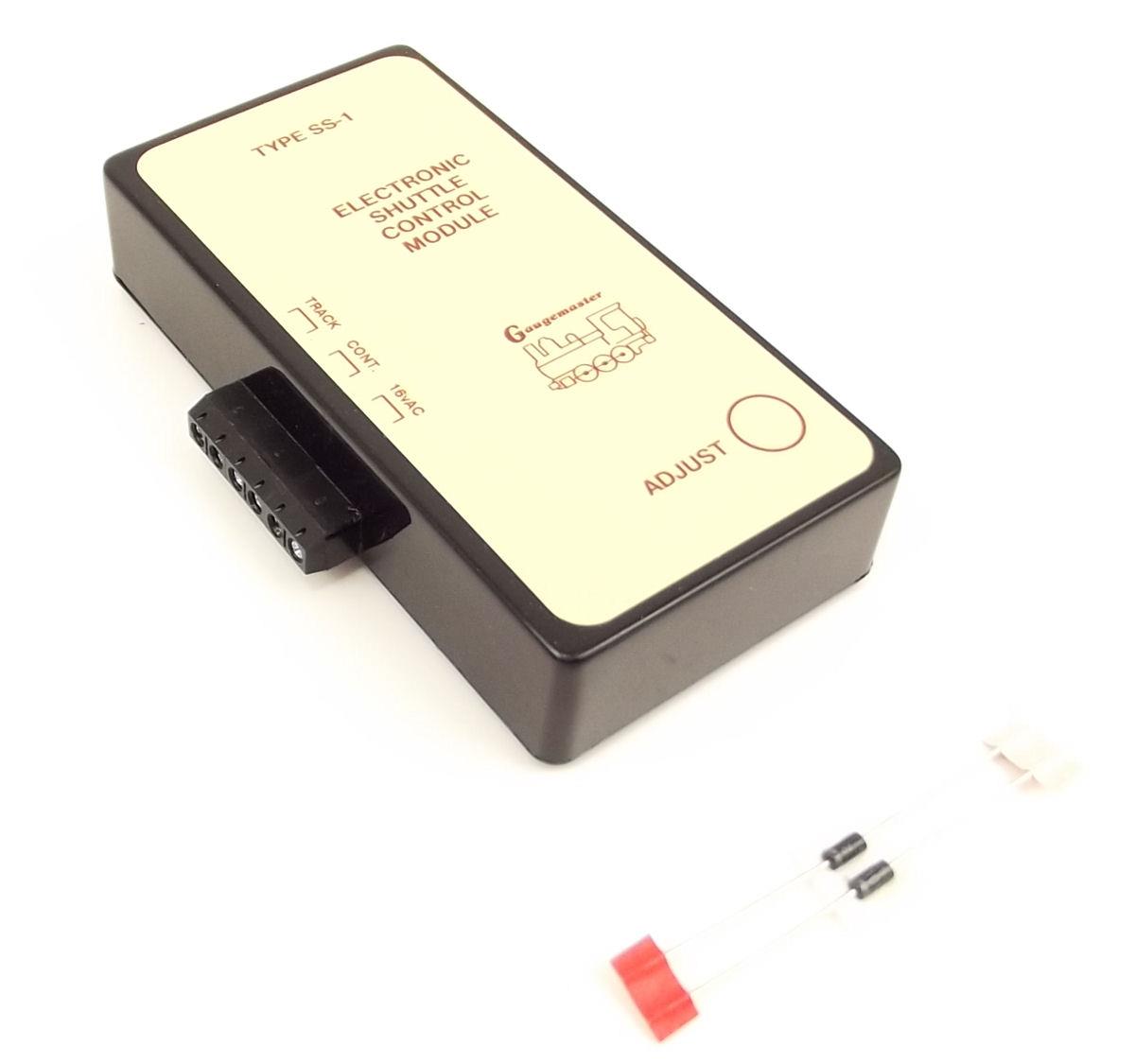
The Shuttle unit comes supplied with 2 diodes; these are used to stop the train at the end of the run.
They do this by acting in the way diodes do, namely by blocking current in one direction, and allowing current in the other - so on an end to end run the locomotive, multi-unit or tram will run to the end of the line and stop, then a short while later, will do the return trip. On reaching the end, it will stop and wait again.
The unit allows adjustment of the cycle by up to 80 seconds by means of a simple adjustment screw, which means it can operate at your desired pace.
A standard controller (such as the COMBI Controller) is used to set the speed of the train, and also to provide a 16 volt AC supply to power the unit.
Click image to view larger version.
Let us move on from setting up a simple end to end run.
Each end of the run needs to have a break in one running rail, which is bridged by the diode. The diode HAS to be the right way round, as if fitted incorrectly the locomotive will not stop in the required position.
Also, if using a loco and wagons, the train will not stop until the last wheel that picks up power has crossed the break; so allow room for the whole train to fit in at the appropriate end.
Click image to view larger version.
For smaller scales (Z, N, TT and OO) the diodes as supplied with the standard SS-1 are fine, but for the bigger scales (O, 1 and G) heavier diodes are needed, hence the unit GMC-SS1LGB is required.
If you are not sure which way the diode goes, hold the diode against the gap, run the locomotive past and it will stop, reverse the power and it will then run in the opposite direction, if all is well the diode can then be permanently fitted.
Click image to view larger version.
If you wish to run more than one train up and down this can be achieved by using Insulfrog points, and extra diodes. As per the diagram, a train (1) will shuttle from A to B, and then, by changing the points X and Y, a second train (2) can shuttle between C and D, and so on.
On the above layout, you can see a 3-way shuttle in position.
Power is supplied to the short length of track in the centre. Each of the three sidings at each end have diodes fitted, so operating the points as required means three individual trains can travel from end to end, even holding them at different ends.
Additional diodes are available in order to achieve this sort of layout.
The shuttle system can be used on a digital layout (not with digital control however) but as a separate line controlled by an analogue controller, perhaps as a tram system, or a small narrow gauge industrial line etc. to add more operating interest to your layout.

This unit allows certain trains to slow down and stop at a predetermined location, wait for a decided length of time, then accelerate away and continue its journey. This unit will unfortunately not work with a digital control system.
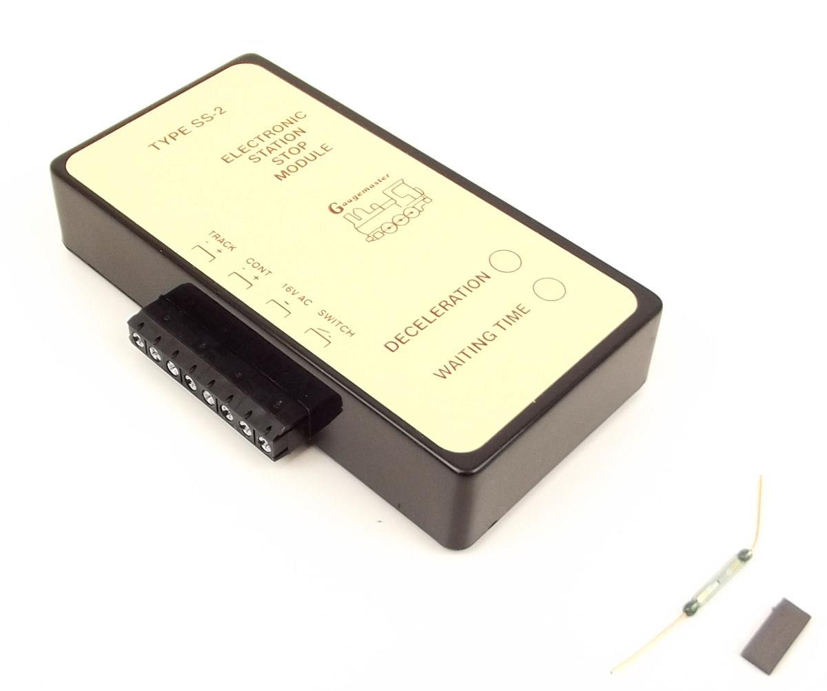
The unit comes with Reed switches and magnets, which form the detection system.
The magnet is fitted to the required locomotive, and the reed switch is positioned between the rails, and connected to the Station Stop unit.
Click image to view larger version.
As the train approaches the location, the magnet operates the switch, the train will then start to slow down and finally stop. It will then wait a pre-determined length of time, then start to move away, gaining speed, and continue its journey.
The slowdown rate and waiting time are once again adjustable by simple adjustment screws. The unit only works in one direction, so the train will not stop in the opposite direction and neither will a non-magnet fitted locomotive - so you can make a (magnet-equipped) passenger train stop at the platform, but a following (non-magnet equipped) freight train will steam straight through.
A certain amount of setting up is required for this unit; placing the reed switch in the right position, adjusting the deceleration time etc, but once this is done no more adjustment is required, unless of course a different locomotive is used, with different stopping characteristics.
If a layout contains more than one required stop, another reed switch can be positioned on the approach as before, and can be connected to the same unit providing enough time is given for the unit to reset.
Click image to view larger version.
A reed switch, as used in the Station Stop unit, consists of a thin glass sealed tube containing two fine metal strips.
When a magnet is brought into close proximity, the magnetic field causes these two strips to be drawn together, thus completing the circuit. When the magnet is withdrawn, the strips part, thus breaking the circuit.
These devices are very useful as a detection device, especially if they are linked to electronic detection devices, or to self-latching relays etc, but do require delicate handling as the glass can easily be broken. Extra reeds and magnets are also available in the Gaugemaster Range.