

 MATT LOVELL explains how to use the new Gaugemaster N Scale Colour Light Signals on an Analogue layout.
During our Open Weekend, in September 2018, a new range of N Scale Signals was revealed, which instantly became a hit with our N Scale modellers. There are six different types of signals in this series which are available in both singles and packs of three. All of them are very nicely detailed including the attached ladders on the appropriate designs. All the signals are fitted with very small LEDs which can be individually operated using a 9-12v DC supply.
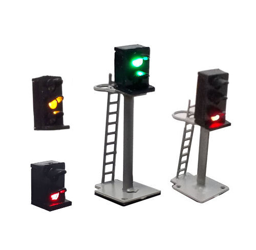
In this article I will focus on the installation of the lineside two-aspect and three-aspect variants and the easiest way of operating them from the required switches on an analogue railway.
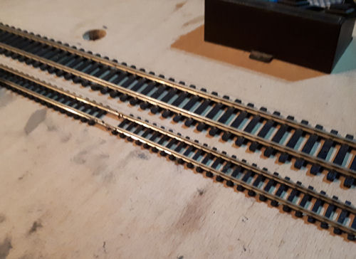
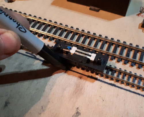
Firstly, you will need to decide where you want the signals to be placed on the railway. I found the easiest way to set the distance between the track and signal to avoid fouling the train was to find the widest locomotive or item of rolling stock and attach a pen or pencil to the side of it with the tip pressing on the baseboard. This can then be used to make a mark on the board showing the distance required between the train and the signal.
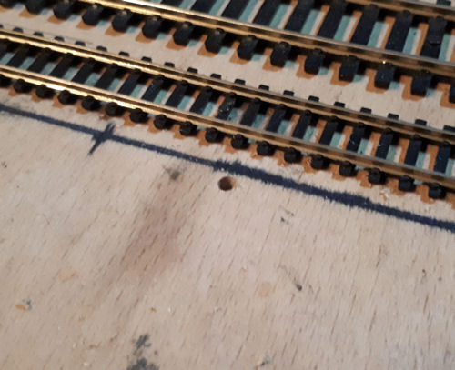
To begin with you, will need to drill a hole to feed the wires from the signal into. I used a 3mm bit which gave enough room for the wires and the attached resistor.
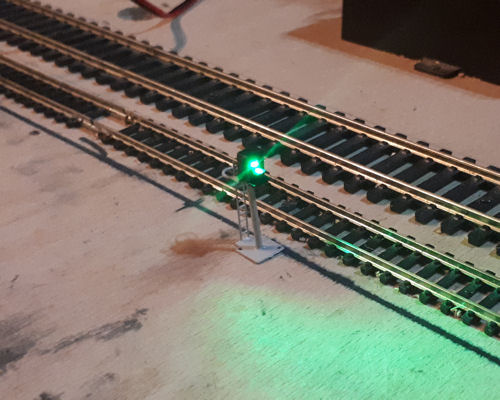
The first signal I am going to install is the GM270 Two-aspect Lineside design.
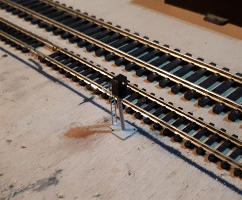
Feed the wires through the hole and then attach the coloured wires to a terminal block, or directly to the switch depending on the distance from signal to switch. The switch I have used for the two-aspect signal is the Gaugemaster GM508 On-On Single Pole Double Throw. The coloured wires on the base of the signal relate to the attached LED inside the head (Red wire = Red LED, Green Wire = Green LED) using these colours you can determine which part of the switch they need to be connected to.
The red and green wires need to be connected to the outside contacts on the switch. The black wire has been fitted with a resistor and needs to be connected to a 9 - 12v power supply. I used the GMC-WM4 12v DC wall mounted transformer. You will also need to connect a wire from the centre contact on the switch to the other side of the 12v DC power supply. This will give power to both the switch and the signal, completing the circuit and illuminating the signal.
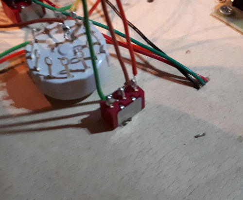
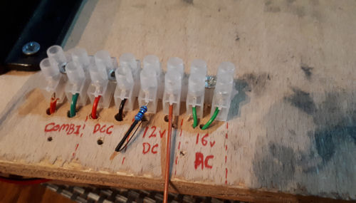
The switch can now be used to change the colour output on the signal.
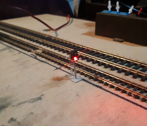
Now we can move onto the three-aspect signal.
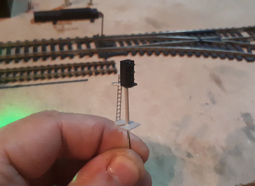
In the same way as before, feed the wires through the hole you have made and connect the black wire to one half of the power supply.
You will have three different colour wires for this signal and in the same way as the two aspect design they relate to the different colour LEDs inside the head. Red Wire = Red LED, Yellow Wire = Amber LED, Green Wire = Green LED.
I have used a GM519 1 Pole 12 Way Rotary switch to control this signal as it has more than two positions and can be used for multiple outputs.
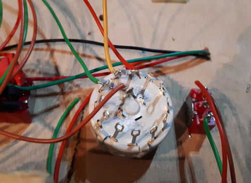
Connect each colour wire to a different terminal on the underside of the switch, I started with terminal 1 and attached the red wire to that so that I had a starting point. I then connected the yellow wire to contact number 2 and the green wire to contact number 3. This will give a smooth sequence between red and green by twisting the switch in the desired direction (Red – Green or Green to Red).
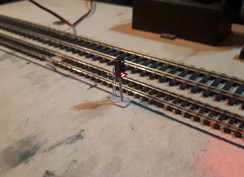
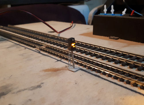
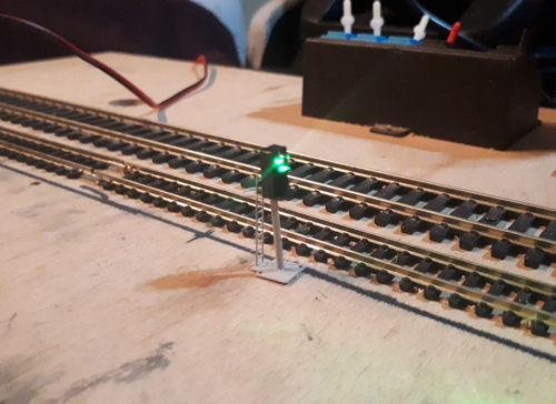
Using this method you can now install lots of signals to your model railway. The next article in this series will focus on using these signals on a DCC model railway.