

ROBIN FRENCH from the Chelmsford & District Model Railway Club explains how an after-school club layout became an exhibition favourite.
Built by Students of the Moulsham High School in Chelmsford.
Students from the Moulsham High School in Chelmsford visiting the Chelmsford & District Model Railway Club exhibition in 2012 felt inspired to build a model railway layout themselves. Through their school’s Head of Design & Technology, they asked the Chelmsford Club if any of their Members would be willing and able to assist - and husband and wife team, Pat and Robin French immediately volunteered.
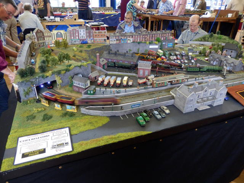
At the first meeting, the Students voted for a circular double-track layout to allow continuous running of their trains, with added features such as a coal mine, a dockyard, an airport and even a fully working volcano complete with sparks and smoke being emitted! The school couldn’t commit to giving space to store any layout larger than 8ft x 4ft., so the idea of an airport was out of the question! The volcano was also rejected on Health and Safety grounds!
It was therefore decided that there would be two oval tracks serving a mainline station. In the centre there would then be a loco yard to store locomotives waiting for their turn on the circuit and a “Heritage Transport Museum” where the Students could display their model cars and aeroplanes. A small station halt would be provided in the middle of the layout to allow visitors to the museum to arrive by train.
Space within the Loco Yard was necessarily very limited, so sidings or a turntable were out of the question. A “traverser” however wouldn’t need as much space, but the problem then was the daunting prospect of scratch-building one!
Money to spend on the layout was always going to be an important factor. Initially, it was proposed to raise funds by selling homemade cakes in the school refectory at lunch times and holding a model railway exhibition but in the end, neither of those options happened. Therefore everything for the layout had to be begged, borrowed or donated.
Because the storage and handling space of an 8ft x 4ft board within the school was a problem, it was cut into three sections, each measuring 32” x 4ft. This unfortunately meant that there were now three boards to join together and at least 14 tracks to join electrically! The baseboards were constructed using 6mm MDF supported by 2" x 1" softwood frames but again - because of the lack of funds and as a kind of experiment - captive bolts were used to align the three baseboards instead of the traditional pattern makers’ dowels.
The layout was first exhibited as a “Work in Progress” at a model railway exhibition held in April 2012 where visitors donated £25.00. A further £20.00 was donated at another exhibition in September 2012 and a Member of the Chelmsford Club donated all the necessary points and point motors from his old layout. Other donated railway items from another source were sold, raising a further £13.00 and with these sums, sundry items such as DIN plugs etc. were able to be purchased. Thus, the whole layout had so far cost a mere £58.00 to build!
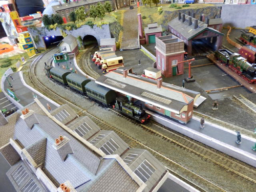
Damaged Metcalfe buildings were salvaged from a waste bin and under the guidance of Pat and Robin French; the students repaired and renovated them all. An old “Twin” D.C. Controller that had also been donated was found to get uncomfortably hot when being used and had to be condemned but fortunately Gaugemaster came to the rescue with two hand-held GMC-W controllers and the necessary transformer. These were gratefully received by the Students and after installation, give excellent train control as well as allowing the Students to operate the points etc. with the controllers in their hands.
With Peco code 100 flexi-track being bought and donated by the School’s Head of the Design & Technology Dept., the students started laying the track on a cork base. To prevent unsightly solder joints being seen on the outside edge of the rail often seen on exhibition layouts, all power inputs to the track were soldered by the students themselves to the bottom of the rail tracks (i.e. “up” through the baseboard). The obvious danger of this method however is if the joint subsequently fails, that section of track has to be lifted to repair it (unless an unsightly soldered joint is then made on the side of the track). That is however the very thing this method is designed to avoid! All solder joints were “Quality Assessed” by Robin tugging as hard as he could to try to break the soldered joint! Failures were done again by the students, but in fairness - they were very few and far between!
Initially track pins secured the track until “N” gauge ballast was added. This was ‘fixed’ by the customary use of diluted mixture of PVA glue and water but pleas to the Students by Robin of "go easy on the ballast" and to "keep it clear of the track itself" were largely ignored by them. They thus gave themselves the unenviable task of chipping off the excess ballast from the insides of the track - a thankless task but a lesson well learnt! When the glue and ballast had fully dried all the track pins were removed.
Attention then turned to motorizing the point motors. Because all the point motors were second-hand, all the previous solder had to be removed from all the connections. This was expertly done by the students using a solder-extraction tool and, once the joint was ‘clean’ again short lengths of wire were attached to the respective point motor connections. These extensions were then connected (through the baseboard) to the point control system detailed in the next paragraph.
The Peco method of “Stud & Probe” was chosen as a cheap and simple method to operate the points - but again, lack of money demanded economies. 2mm bolts were therefore used as electronic “studs” for the “probe” to touch, and that in itself, was a redundant “wheel scraper” from Peco’s Wheel Cleaner & Brush set. These bolts were drilled through layout’s 2" x 1" frame on the Operator side of the layout and a wire then ran to the appropriate point connection. Ultimately perhaps, when more money becomes available, a proper track plan with ‘proper’ Peco studs might be made - but that then will involve more wire connections between the three boards and the control panel!
Apart from the two dozen Metcalfe buildings salvaged (above), one building (the “Old Mill”) was scratch-built by the students using the school’s C.A.D. computer. The school’s laser cutter was then used to cut-out the final design - including the paddle wheel and paddles. A 6-volt motor and gearbox was added to motorize the wheel and a hole was cut into the baseboard to simulate the waterwheel being cited in the mill-race.
Pat and Robin also donated most of the scenic material with more help from Gaugemaster. Pat introduced the students to her static-grass electric applicator. The Noch grass fibres are then sifted falling vertically onto the glued surface of the layout because of the static electricity generated by the unit.
The only problem with applying the static grass however was the over-enthusiastic use of the (cheap) hair spray by one particular student to secure the scatter material - we all went home those days smelling like the inside of a ladies hairdressing salon!
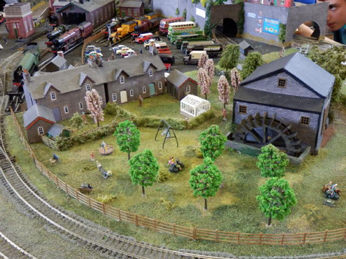
Because space in the middle of the layout was becoming limited with the room required for the loco yard and Transport Museum, the decision was made to place the renovated low relief Metcalfe houses (below), on to a tunnel and ultimately have them as a back scene to the layout.
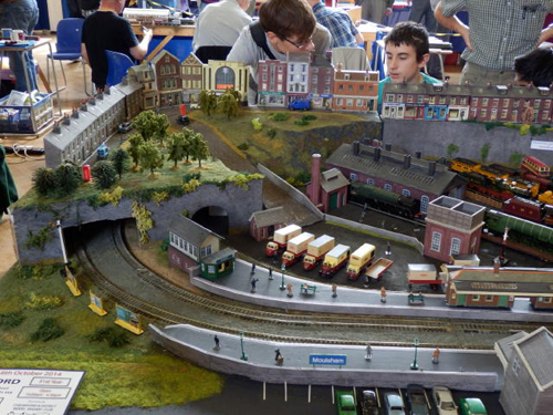
The tunnel (like everything else) had to be light, portable, and removable for storage and exhibition, so the decision was made to make it out of foamboard strengthened by 5mm sheet of plywood. The Students then came up with the new idea of a ‘fiddleyard’ where locos and trains could be changed out of sight of exhibition visitors! Because of the limited height within the tunnel, the only place a fiddleyard could be built was on the back straight on the Operators’ side of the layout. To hide this fiddleyard, a walled-embankment was therefore made as an extension of the tunnel / backscene, where some more low-relief houses were sited. The Heritage Transport Museum station halt emerges from a tunnel mouth set into the brick embankment.
And that is more-or-less where the layout is now (October 2014). There is still much more to be done - the next major step being to mechanise and provide power to the Traverser and loco yard sidings but already the layout has received much acclaim.
Visitors to an “Open Evening” at Moulsham High School for the parents of next year’s intake of students were amazed at what an “After-School” Club had achieved in just two hours every Wednesday for approximately 74 weeks (two academic school years) - and all for only £58.00...
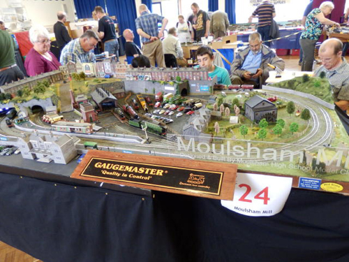
Furthermore, at the recent Mid Essex Exhibition held in September 2014, there were never less than half-a-dozen visitors around the layout at any one time that included families as well as “seasoned” model railway enthusiasts. Everyone said they thought it wonderful to see a school and its Students getting so involved in making a model railway layout.
But it didn’t stop there. The Exhibition Managers of both Romford and Shoeburyness Model Railway Clubs saw the layout at Mid Essex and have booked the layout for their respective November exhibitions in 2015 when hopefully, the layout will have the Traverser working and “lights” in all the houses - maybe even street lights...
Finally, in building this layout, the Students have learnt and developed an awful lot of modeling skills These have included basic carpentry (building the baseboards), working to precise measurements, making the models and track alignments correct as well as electrical soldering, circuit wiring and laser cutting. And that’s to say nothing about what they have learnt about our Railway History and Heritage...
Robin is a member of Chelmsford & District Model Railway Club, and his own layout "Engaine-cum-Hardy" was featured in the September and October 2013 issues of Railway Modeller.