
 PAT PETTETT looks at what is involved when redesigning a demonstration layout.
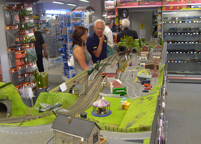
Those of you who frequent our shop will be more than familiar with our shop display layout and have probably watched it change and evolve over the years as we have added new products to it. It has been a very useful display for us, both from a modelling point of view and of course for testing. Over the course of time we have literally moved mountains on it, as seen here, chopping away hills and building up others to suit the needs of the day.
The layout was originally born in Germany, as a Marklin factory display layout. Trains ran in the same direction in sequence, with an automatic timer running one train round after another. A Faller fairground occupied the space by the station, and a single line ran behind the platforms towards a three track engine shed. A Faller car system ran from one end of the layout to the other, with return loops hidden under the hills at each end to enable cars and trucks to circle indefinitely. At the mountainous end was a village overlooking the bridges and valley area.
As a factory layout, it was often taken to shows in the UK and I remember taking it to Warley soon after joining the company. (We have redacted the date as not to embarrass Pat too much - Ed). After being retired from the exhibition circuit, the layout sat in storage for a few years before the decision was made to see if we could anglicise it for use in the shop. An assessment was carried out to see how much work was required as the track was Marklin 3 rail AC, not 2 rail DC.
As long as all points were removed, we could use it to run both analogue and DCC, with one loop dedicated to each. Space was made in the shop, and over the course of several months we replaced the track in the station area, removed the Germanic buildings, and refreshed the scenery on the whole layout.
The layout as seen after its first anglicisation.
Over the years since, it has given sterling service but it has limitations as a working layout. It was built with German made stock in mind, the curves at each end are Continental radius one, 360mm or so, which almost all of the continental manufacturers use as their minimum. This is much tighter than what has become the UK minimum radius – set track radius 2 or 438mm. As a result we are unable to run longer wheelbase British models on it. The tunnels are also an issue thanks to the 'continental loading gauge' most British stock can jam itself against the tunnel walls too and there is also very limited clearance to remove anything that derails in the tunnels. This is something that has become worse over time as our changes to the scenery have reduced the clearance even further.
There are many recent product developments that we would like added to the layout, but the underlying structure has now been modified so many times that it really restricts what we can add or wire in. Thoughts started drifting to what we could do about that.
Pardon? Initially this almost sounds rude! But when designing any new layout you need to go over what you actually want the layout to do for you. There is nothing more frustrating than building a layout then finding out that you can’t run a specific model, or you suddenly take an interest in a particular industry and find there is no room for it. So we ask ourselves what do we want, and what must the layout do?
We need a double track main line, both for scenic and operational reasons, as we need to be able to test and demonstrate both DCC and Analogue models. We want height variation, as this adds immensely to the scenic aspect, and we also need a higher level area to add something that our current layout lacks – an N gauge test area for both DCC and analogue. Narrow gauge is our friend here, as it allows us to have 9mm gauge track available for testing, whilst keeping the same scale across the layout. We also need a fractionally larger layout, so that we can fit the second radius 438mm curves so that all British models can be run. We want the same scenic variation that our current layout gives us, with both countryside and more urban areas. As a result we will be able to keep a lot of the existing buildings, and we will keep the high street area, industrial area and housing area. Finally we want a layout that is easier to work on if, actually when, we decide that some whizzy new model deserves to be added.
There is nothing inherently wrong with the basic premise of the current layout, so we will be keeping with that. In effect what we are doing is our own interpretation of 'that layout that you really liked at that last exhibition you went to'.
How big is it going to be? Luckily for us we do have a bit of room to play with and we also have an added bonus that as this is intended for the shop, we can access it from all sides. For a home layout, we would need to keep the track as simple as possible in the areas that are hard to reach, namely the back rear corner. Otherwise you can guarantee that you will get a derailment there, and simultaneously discover that your arms aren’t four feet long!
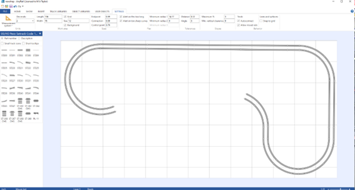
We measured up the current layout, and then fired up our track planning software, in this case 'Anyrail' but there is other software on the market, both free and paid for, to find out how big the layout ends need to be in order to fit in our desired double track in about the same space as the current layout. As the layout is L shaped, we can keep pretty much the same general size, and the increased width to accommodate the curves can fit on the inside of the L. We know from Hornby train sets that a board 4 feet or 1200mm wide will accommodate the curves we need. After entering our size in the menu at the top, we can drag and drop the curves into place.
Now that we know what we want will fit in our available space, we can look at the cost of the boards. Three sheets of 6mm MDF for the base top itself, and as MDF is very stiff we can reduce the amount of cross bracing underneath, however even with that in mind we need 22 metres of timber (25 by 75mm) to form the frame that will support the top. Having the frame 75mm deep will allow us plenty of space underneath for point motors and other electrics like signals and cables for lighting.
The current layout is made of three sections. If this was a home layout then the need to move it would be a minor consideration, but as this would live in the shop we could need to move it so we have retained the same three section idea as before. As previousley mentioned, the layout was transported frequently to exhibitions so the need for manageable sections were a must.
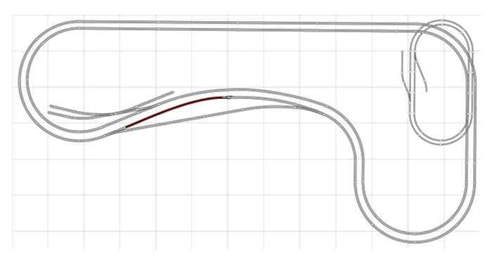
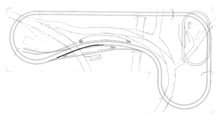
In our design we have used Peco Setrack for the ends to ensure a constant radius, and left the “station area” slightly askew – this will be more interesting visually, as we will have a curved, natural look to the station. By fitting in this reverse curve, we are also reducing the length of the right hand end of the layout to save space. We now fill in that station area to see what we will be able to fit in it.
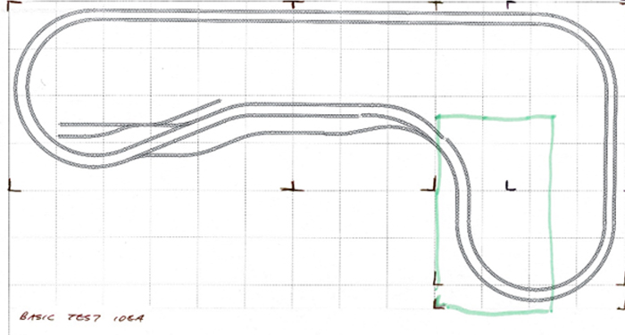
The faint green rectangle is my first idea of where the raised narrow gauge would go, I later moved this to give a more natural flow to the scenery. The little check marks visible around the plan are ideas of where the baseboard joins could be. At this point I am still using Setrack, just to see what will fit. I always find that this looks rather 'forced', so we will now convert that station area into streamline flexible track and points resulting in the following.
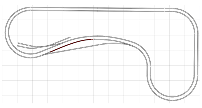
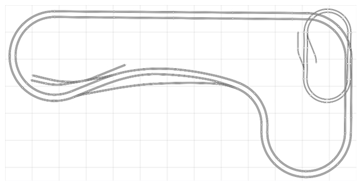
The outer loop will be the DCC one, the passing loop allows us to park a train there whilst we test or demonstrate another without having to manhandle the existing train. On the analogue inner loop, we can back a train into the small goods yard to park it. The mix of DCC and analogue means we have no connections at all between the main loops – if this was a home layout and controlled from DCC or Analogue, not both, then we would add crossovers at each end of the station, so that we could run around trains and shunt freight into the sidings from both sides for example.
As with the current layout, we would keep the raised areas at each end to tame down the visual impact of the curves on the main line, and on one of these raised corner areas we now add the double track narrow gauge section.
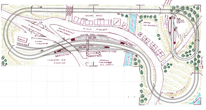
At this stage I am already thinking what scenic aspects will go where, so its time to print off a couple of copies of the plan and start scribbling away on them to fill out the layout. Below is the first proper 'fleshing out' of the skeleton I’ve made so far.
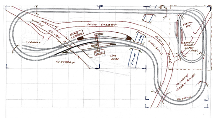
The first scribblings are visible in pencil, with ink used once I’ve started to become more certain about what will fit where. A few things obviously need to be moved, for example the canal section will need to be aligned to the left at the top, so that it doesn’t cross a baseboard join.
Where the upper level road crosses the whole layout on the left side, I really wanted slip roads down from the upper road to a small “roundabout” of sorts under arches that then connects to the high street. However, it is soon obvious looking at the plan above, that there isn’t a massive amount of space between the bridge over the station, and where the main road leaves the layout at the top left of the plan. As a result, any slip roads there would have to be very steep, not something that I would want to drive down and not something that will look sufficiently natural. Time to grab some track, and see how it could actually look and see if I can find a way to fit in what I wanted.
With the second and third radius corner laid out, I’ve used Bachmann boxes as a rough guide which are 3 ¾ inches high, more than enough clearance for OO models. Even with the fact that the road level will be at the BOTTOM of the boxes used as bridges, the Plastruct strips I’ve used to demonstrate the gradients show it is much too steep for my desired slip roads,
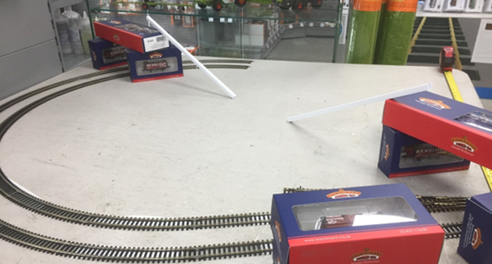
There is nothing at all that says however, that the bottom road level must be at the baseboard level. The solution then, is to raise the base level of the road at that point. More Bachmann boxes!
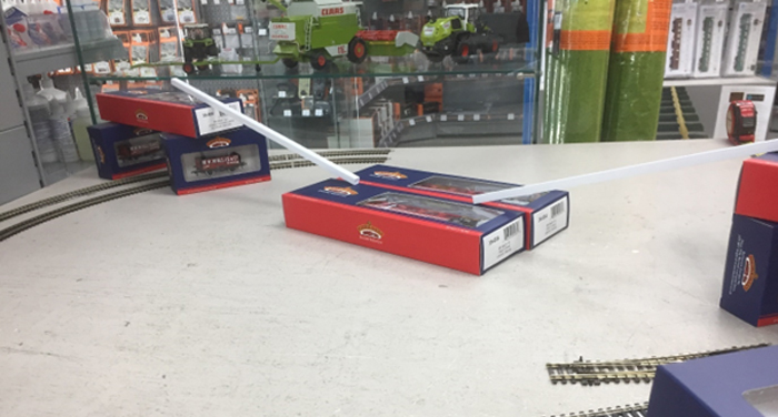
This is a much nicer gradient. When we factor in that the road surface will be at the BOTTOM of the bridge boxes shown above, there is more than enough room for the lower roundabout along with slip roads from both directions without them being too steep. Having a higher baseboard at this point will also mean I can easily fit in a loading dock up against the goods yard sidings. Now that I’ve actually seen that it will fit, I can go back and re-draw that end of the layout.
I’ve also checked the other area where clearances could be an issue too. The high street beyond the station is another area. Taking the deepest building that we have on the high street of the current layout, the Cinema, I’ve done similar tests to see if there is enough room for, from back to front:
It turns out there is, well, just. This is the worst case scenario, assuming that the Cinema would be located opposite the platform at the widest point. Again there is nothing saying that the Cinema has to be located there, it can easily sit at the end of the high street. If needed, we can always remove or shorten the two short straights at the east end of the station, and slew the entire station a few inches toward the edge of the board, as there is plenty of space to do so without affecting the character of the layout. So time for more scribbling so I can envisage where we are now.
At this point, you can see I have started to experiment with exactly where the road goes on the right hand end by the curve, and I am thinking that more space there would indeed be more useful than space on the inside of the L where the station car park will be. Time to go back to Anyrail and shorten the standard length straights before the station curve to half length straights. This will pull the entire station area towards the inside of the L, I’ve also swapped the standard point that gives access to the goods yard for a large radius Y point. This keeps a nice even flow through the station area
I can now redo the scribble to decide on final, honest, positions for things.
At this point I would be happy to go ahead. Whilst we will not be demolishing the current layout just yet, I'm happy with the design itself. Here we have shown that we can preserve all of the operational and scenic elements and the approximate size, whilst updating the design to be more useful for current rolling stock designs and requirements. If you do find or see a layout that inspires you, ask the exhibitor if you can take a few pictures, ask them about dimensions, how they designed it etc. Many owners would be happy to talk to you and share their experiences, and even pitfalls of their own designs. then, grab some track planning software and some of the basic parts you will need, and have a play with them! You may well be amazed (and hopefully proud) of what you can come up with!