
Most modellers throughout the years will have created a reverse loop somewhere along the line, many unwittingly. This has caused re-designs and reworking of the track to avoid such an incident, but what exactly are reverse loops?
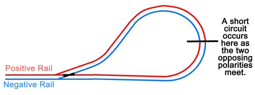
In simple terms a reverse loop is just that. A simple loop of track that reverses back upon itself allowing locomotives to enter and exit the loop locomotive first, without the need of a turntable, or to uncouple the locomotive at all. Sounds ideal but in reality if simply connected up you will find that the track forms a short and trips out any controller. The reason for this is again simple. Regardless of the type of control, analogue or digital, the same problem exists. If we think about it in terms of analogue control the following happens. The positive rail is permanently connected to the outside rail, which when returning at the point, comes into contact with the negative rail. The same happens on the inner rail with the negative coming into contact with the positive.

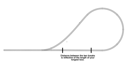
The solution to the problem differs depending on whether you are using analogue or digital control. For this part we will concentrate on curing the problem using analogue control, and move onto the wiring for digital control in part 2. So now we know the problem, we can work out the solution. Using no more than some layout wire, isolating fish plates in the scale you are using, and a DPDT switch, a solution can be constructed. Insert the isolating fish plates into the loop in the positions shown in the diagram below. One fish plate on both rails at both locations. This will create a fully isolated section within the reverse loop, stopping the short.

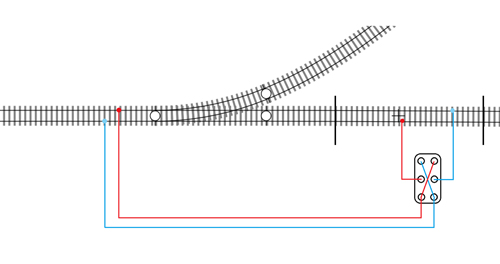
The problem now is that you have a situation where there is an isolated section that the locomotive cannot continue over. This is rectified with the addition of the DPDT switch. The DPDT or 'Double Pole Double Throw' switch will be responsible for changing the polarity in the isolated section. The wiring for this is shown in the following diagram.

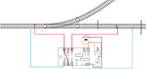
Once this is installed your reverse loop is wired up and ready to go. All you need to do to operate is simply drive your locomotive round the loop and stop it in the isolated section. Then simply flick the switch, and drive the loco away. This will work for any analogue layout, with or without a point motor installed. If however, you do have a point motor installed, you can wire up the reverse loop to change the polarity with the throw of the point motor. To do this you will also require a GM500 Universal Relay Switch. This takes the place of the switch and wires up in a similar way, see below.

Once installed it will work in the same way as using the switch, except this time you only need to throw the one switch to throw the motor and change the polarity. You may find that the unit is reversing the polarity in the opposite way to that required. If this is the case simply swap the two wires that are connected to the GM500 on terminals 1 and 4, and you will be away.
That has covered the basics for reverse loops in analogue, and in Part 2 we will look at reverse loops on a digital layout. If you are looking for the more advanced reverse loops and triangle situations, keep your eye out for Part 3, reverse loops and advanced polarity problems.
James can often be found underneath our shop layout - he claims he's fixing wiring but we think he's just hiding...