

 JAMES HICKMAN shows us more advance ways of using this innovative product.
It has been a couple of months since the first part of this series of articles went out, and as some of the eagle-eyed amongst you will have noticed, we sold out of the Smart Screens very rapidly. They are now back in stock which has given me the excuse to have another play with these amazing units and see what else they can do.
I am not going to cover the basic programming in this article, as this was covered in Train Tech Smart Screen Part 1, but I am going to focus on the more advanced, but still easy, ways of controlling and operating these wonderful little screens.
Firstly, lets recap what we did in the previous article. Aside from the programming and wiring up of the Smart Screens, I showed you how they can be enclosed in the additional housings for use on your platforms for departure boards. We mounted these on a platform and left them running through the default programming in "loop mode." This means that the units simply cycle through the list of programmed displays. Since writing the article, Train Tech have produced a Free PDF Download  to help you to plan out the text for the display boards.
In this part of the series of articles I’m going to show you the ways these units can be controlled. Firstly, a note for non-DCC Users. This does not rule you out. Some of these controls are unique to DCC but some aren’t. So don’t stop reading yet!
To show which control methods can be used for DCC and Analogue users, I’ve separated the different controls into scenarios and noted which can be used for Analogue and which for DCC. Please note, analogue users will need access to a DCC System to initially program the Smart Screen, but afterwards will only need to power the unit. Feel free to use the text in the examples below if you haven’t quite decided what you want your destinations and text to say yet, and just fancy having a go.
(Analogue and DCC Applicable)
In this scenario we will be looking at is control of the Smart Screen by way of track sensor. We will use the sensor to change the board from showing the upcoming train to announcing its arrival.
Please expand the video to "full screen" in order to see the operation in detail.
The first thing to do is to program up your Smart Screen with the required messages. If you are unsure how to do this, please refer to part one of this article series. We will be using the messages stored in Message Slot A and Message Slot B. Start by programming the message into Message Slot A. This is the message that will be displayed prior to the train arriving. In our example I have set the message to read:
12:58 LONDON VIC…
Calling At: Ford, Arundel, Horsham, LONDON VICTORIA
Message B will be displayed as the locomotive activates the sensor. This reads:
** STAND CLEAR**
TRAIN IS ARRIVING
The final stage of the programming is to assign the control a DCC Address. Although it will not be using this address, this will make sure the Smart Screen does not cycle the messages without the sensor being activated. To do this, call up the loco address of the unit (the default is 55) and activate the functions in the following order; Function 8, Function 5, Function 5, Function 6. Finally use your controller to activate an accessory number that you do not already use on the layout. I would suggest a high number that will not be confused with any existing accessory numbers. For Gaugemaster Prodigy users, you would simply press "ACC" on your handset, followed by the accessory number you wish to activate, then the ENTER button, and finally 1 then 2 on the handset. For users of other systems, consult the manual of your controller on operating accessories.
Once the above is programmed, it's time to add the additional TTST10 Sensor to the layout. There is a small difference to installation depending if you are an analogue or digital user:
For DCC users: Plug your track sensor into the track, a short distance away from the beginning of your platform. If you are unable to plug the sensor directly into your track, follow installation for analogue users below.
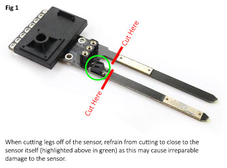
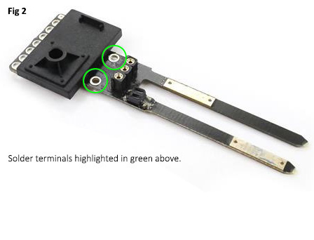
For Analogue users: Cut back the two legs of the sensor along the point shown on the diagram above (Fig 1). Once this is done, solder a wire onto each of the solder pads highlighted below (Fig 2). The two wires can now be attached to the power supply. Please note, these wires must be connected to the same power supply as the Smart Screen power feed wires. Now the Sensor can be mounted adjacent to the line, a short distance away from your platform.
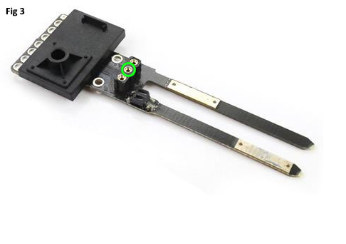
Finally, for both analogue and DCC users: the last step is to connect the Sensor to the Smart Screen. On the back of the Smart Screen, there are additional solder pads marked A and B. A final wire needs to be attached to the solder-pad marked A. Once this is done, simply push the other end of this wire into the middle hole on the track sensor as highlighted below (Fig 3).
Once this is all connected, you are ready to go. Power up the layout, and as your train passes the sensor, you will notice your message change. After a few moments this will revert to the previous message and begin the cycle again.
(DCC Applicable Only)
This scenario we will look at is the screen changing depending on the route the points are set. This one is for DCC Users only as it requires the activation of the points via digital control.
Please expand the video to "full screen" in order to see the operation in detail.
The video above shows the Smart Screen displaying a message detailing the next service to call at this station. We have a train due to travel through our station and one that will be heading down the branch line after stopping. The screen will change to show the branch line service once the point has been thrown. To program this scenario up, you will need to use two Message Slots. In the previous example we used Message Slots A and B. For this example, we will be using slots C and D.
Message Slot D is programmed to display the following:
12:58 LONDON VIC…
Calling At: Ford, Arundel, Horsham, LONDON VICTORIA
Message Slot C is programmed to display:
12:51 WORTHING
Calling At: Angmering, Goring, Durrington, WORTHING
Finally, you need to assign the address the change is going to be controlled by. In this case it is the throw of the point. Our point has been set up under accessory number 1. So, to set the Smart Screen to respond to this by selecting the smart screen address (the default is loco 55) and activating Function 8, then Function 5, then Function 5 again. This will take you to the following screen:
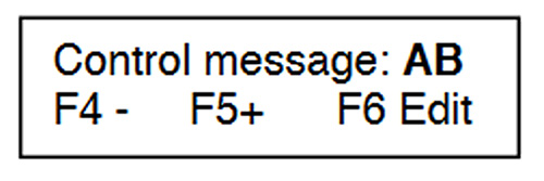
Now using the Function 4 and Function 5 buttons, scroll through the list of pairs until the one you are using is on the screen. In the above example we pressed Function 5 once to change the displayed pair from AB to CD. Once the correct pair is selected, press Function 6.
Now the Smart Screen is waiting for you to activate the accessory you wish to bind the Smart Screen with. For Gaugemaster Prodigy users, you would simply press "ACC" on your handset, followed by the accessory number you wish to activate, then the ENTER button, and finally 1 then 2 on the handset. For users of other systems, consult the manual of your controller on operating accessories.
Once this is done, the screen will save the command and default back to the operation screen. Now you are set up and ready to go. You can add additional messages activated from different accessories by using another pair. For example, we are using pairs C and D combined with a point in the above example, you could add a second pair of messages in E and F to change when a second point is thrown, or a signal is set to clear. One us of this could be that the Smart Screen changes from displaying the destination board to displaying ‘Please Stand Back This Train is Scheduled to Leave’ when the signal is set to green.
(DCC Applicable Only)
This scenario will show you how to control the Smart Screen from locomotive functions. You can change the display when you activate a specific function of a locomotive, which is perfect for any modeller running their layout to a timetable.
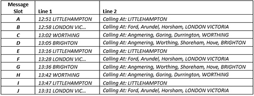
Using the function commands of a designated locomotive number you can activate and display any of the 10 Message Slots, Message Slots A through to J, at any time. To set this up, you just need to fill the Message Slots with your required Messages. Example 1 below shows purely a list of timetabled departures:
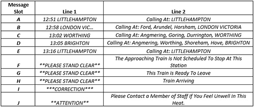
The second example below shows a mix of time tabled trains and possible warnings:
Once your messages are programmed in, you will need to decide which loco address you wish to use to control the messages from. I would suggest 99 as this number is not normally on a loco would be numbered to, but the choice is yours. You will need to set the Smart Screen Address to your chosen Address. Please be aware that you must set it to an unused address, and one that is different from the address already set in the unit for its programming address.
To set the control address simply activate Function 8, then Function 5, then Function 5 again. This will then take you to the following screen:

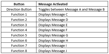
Now use Functions 4 and 5 to adjust the on-screen number, pictured as 0008, to the desired number, then activate Function 6 to save. In my example I would have changed this to number 99. Now you are all set to go. To activate the different screens simply call up the locomotive with the number chosen, in my case number 99, and activate the screens by pressing the buttons outlined below:
That’s it for Scenario 3, a quick and easy one for DCC Modellers.
(Analogue and DCC Applicable)
This scenario involves controlling the Smart Screen from an external source. This could be a variety of options for example a push-button switch, a reed switch, a relay or even a servo. This example shows how the Smart Screen could be controlled by either a Push-Button Switch or a Reed Switch.
We have a freight locomotive due to travel through our station which won’t be stopping. As customary on the mainline, a warning flashes up telling all passengers that the train is not stopping and to stand clear. The screen changes to this once the push button has been activated and allows the non-stopping service to continue through the platform before the screen reverts to its original display.
The screen is programmed up in the same way as Scenario 1. The first thing to do is to program up your Smart Screen with the required messages. If you are unsure how to do this, please refer to part one of this article series. We will be using the messages stored in Message Slot A and Message Slot B. Start by programming the message into Message Slot A. This is the message that will be displayed prior to the train arriving. In our example I have set the message to read:
12:58 LONDON VIC…
Calling At: Ford, Arundel, Horsham, LONDON VICTORIA
Message B will be displayed as the Push Button is pressed. This reads:
** STAND CLEAR**
THIS TRAIN IS NOT SCHEDULED TO STOP AT THIS STATION
The final stage of the programming is to assign the control a DCC Address. Although it will not be using this address, this will make sure the Smart Screen does not cycle the messages without the sensor being activated. To do this, call up the loco address of the unit (the default is 55) and activate the functions in the following order; Function 8, Function 5, Function 5, Function 6. Finally use your controller to activate an accessory number that you do not use on the layout. I would suggest a high number that will not be confused with any existing accessory numbers. For Prodigy users, you would press ‘ACC’ on your handset, followed by the accessory number you wish to activate, then the ENTER button, and finally 1 then 2 on the handset. For users of other systems, simply consult the manual of your controller on operating accessories.
To complete the set-up, all that is needed is to install the switch. This can be installed wherever you like on your layout. Then attach one side of the push button switch to the A terminal on the back of the Smart Screen, and the second wire to the C terminal. Once connected, power on the Smart Screen and enjoy.
(Analogue and DCC Applicable)
The above two scenarios work happily as outlined above - however, for DCC users both Scenarios 1 and 2 can be combined. All you need to do is set them up as outlined above, making sure the data in Scenario 1 uses Message Slots A and B, and the data in Scenario 2 is in Message Slots C and D, and you will happily find that both control methods can be worked together.
Please expand the video to "full screen" in order to see the operation in detail.
You can also combine these with additional inputs as described in Scenario 4.
For Analogue and DCC users, you can combine Scenario 1 and Scenario 4, using both the track sensor method and an additional input device. There are many options with this, so just have a play.
That’s All Folks... For Now.
I hope this has shown you all some additional ways the Smart Screen can be used and controlled, but that is just scratching the surface. Whether you are using the Track Sensors or push buttons, or even binding them with accessories, the possibilities are endless. In the third and final part of this series I will be looking at other uses for the Smart Screens and ways of combining them with other parts of the layout too.