

 JAMES HICKMAN looks at how to use this innovative new product from Train-Tech.
With Digital Command Control becoming more and more commonplace in layout operation, it was only a matter of time before more and more interesting elements were introduced by manufacturers. We have seen digitally controlled couplings from the continental manufacturers as well as opening doors on rolling stock. Now it's the British market which is making the leap and Train-Tech have done so with the introduction of their Smart Screen.
The Smart Screen deployed on our layout.
For those of you that haven’t come across the product yet, the Train-Tech Smart Screen is a miniature screen designed to mimic the display screens found on platforms, on the side of trains, and even those in buses or coaches, as well as any other location these screens are found.
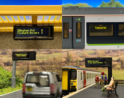
Just a few uses of the Train-Tech Smart Screen.
This one is easy to answer - it is not simply a module that lights up. The Train-Tech Smart Screens, primarily designed for OO Scale use, can be fully programmed to display any message that you want. If you would like them to display the upcoming departures from your platforms, they can. If you want them displaying the destinations on the side of a coach, they can. The units do require a DCC Controller to program them, however once programmed they will happily operate from a clean 16v AC supply.
Before installing the screens, it is first a case of deciding what they will be doing. Train-Tech additionally produce a range of holders for the Smart Screens, two post mounts (left and right options) and a hanging mount. The post mounts are designed for free standing departure boards like those found at station platforms, and the hanging mount is a simple box to fit around the Smart Screen, allowing it to be hung or mounted in a coach, or even on a wall.
Secondly, it is a case of deciding what you would like the unit to say. This bit is key as if it is not properly planned out, the following stages can become frustrating and repetitive. For this article, we will be setting up a Smart Screen with a platform mount to show the next trains departing from our platform.

The Plan for each of the platform signs and their text to be displayed.
It is always good when planning your layout to have in your mind aspects of the layout which effect how it will be modelled. I would consider drawing a rough map to help you plan this out to make sure your station signs correctly reflect the area surround the model. It will also help when positioning any road signs too. For added realism, another thing to consider here is the time you have your trains arriving and departing. This is best suited to morning or evening schedules as many scenes on layouts take place during this period. For example, you wouldn’t want your times set at a point in the evening if you have a postman delivering your post a few streets away from the platform.
The Smart Screens come pre-fitted with six solder pads on the back. Care is needed when soldering these as if too much heat is applied, the internal connections may become damaged. A small quick touch with a 25w iron should suffice. There are two connections that everyone will be using. These are marked with a letter 'P'. These are your power input. Simply solder a wire onto each of these and you will be ready to program.
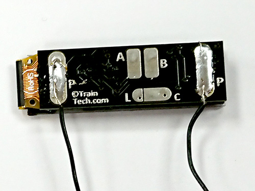
A view from the rear of the unit. The screen is fitted with a plastic cover on the front, do not remove this until installation is complete.
The additional pads are used for other purposes. The pads marked with 'A' and 'B' are control input pads. These are used if the Smart Screen is being connected with Train-Tech's Track Sensors or their Sensor Signals. The pad marked 'C' is the common input pad, and the pad marked with 'L' is the screen reset pad. In this example we won't be using anything other than the 'P' pads, however a future article will cover additional uses. If this is something you could be interested in doing, attach the wires to the additional terminals (excluding the 'L' terminal) and leave the cables loose but isolated for future use.
Now that we are connected, the programming can begin. Firstly, a note how the Smart Screen programs. The unit needs to be connected to the MAIN TRACK output of your controller, and not a programming track output if it has one. This is down to the Smart Screen being programmed by way of loco accessory commands. The default address of the Smart Screens is 55. If you have a locomotive on your layout with this number, you will need to change the address of the Smart Screen to another number. For the two I am installing here, the numbers 9991 and 9992 were chosen as they are completely different to any locomotive running on our layout. To change the address of the Smart Screens, simply refer to the enclosed instructions.
Once this is done, we need to call up the Smart Screen address on our digital system. As previously mentioned, The Smart Screen addresses are locomotive addresses, so simply select it as you would a locomotive. In this case I would select locomotive 9991 for the Smart Screen destined for platform 1, and 9992 for the Smart Screen on Platform 2. On initial start-up the Smart Screen will display a pre-programed message. To begin programming, activate Function 8, and this will bring you to the following screen:
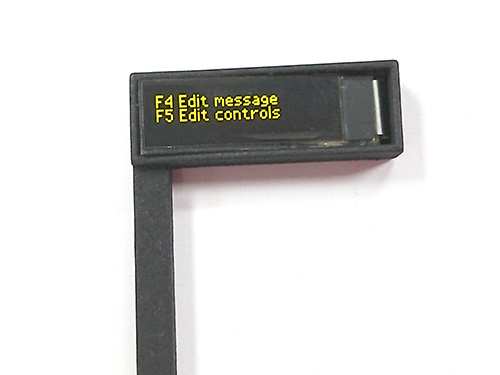
You will now notice the Smart Screen has been fitted into the Smart Screen Right Hand Post Housing mentioned earlier.
Here you have the option to edit the messages stored on the Smart Screen or edit the controls. As we are only programming the basics in this article the controls will be explored in the future article. For now, we simply wish to edit the messages. Be warned that once you pass this step, the pre-loaded demo message will permanently be deleted. Activate Function 4. You will now be faced with the following screen:
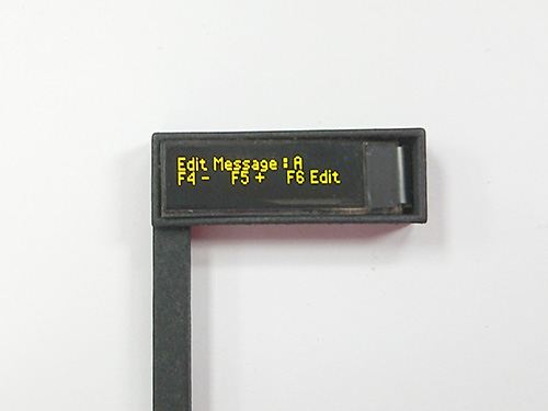
This screen is now asking which message you wish to edit. For your first message, you need to simply Activate Function 6. If you are adding additional messages, simply use functions 4 and 5 to cycle through the letters A-J to choose the desired slot.
You can program one message in each of the letters A-J making 10 in total. The following screen will now appear.
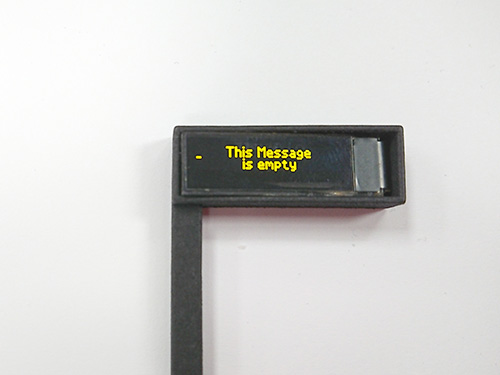
Now is the time to start adding the first line of your message. Use the Functions as described below to add your messages:
This line will only display what is shown on the screen. If you wish to insert a clock, do this to begin with so that you know how much space you have for your text. Once the line is complete, simply fill the remainder of the line with spaces by pressing Function 1. Once this is done, the cursor will automatically drop to the second line.
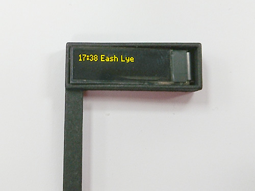
Here simply repeat the process as described above for the second line of text. A note here is simply that this line can hold up to 137 characters. Once the initial amount has been entered, the text will disappear to the left. Don’t worry, it is still there and once the line is complete the Smart Screen will display this as a running banner as seen on real platform screens. To end the line of text, add a few extra spaces. This will ensure there is a gap between the final letter and the first letter when the scrolling line repeats.
Once that line of text is complete, all you need to do is activate Function 8. The unit will then jump to displaying your message. If you wish to add additional messages for the screen to cycle through, simply repeat the process as described above.
Once you have programmed your Smart Screen as you require it, it's simply time to install in into the location you want it. Once attached in place, connect to either your DCC power bus or a clean 16v AC power supply and enjoy the fruits of your efforts.
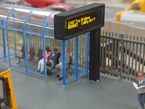
The finalised Smart Screen in place and powered up.
From here we repeated the process for the second Smart Screen located on the opposing platform. The Smart Screens are available singly for those wanting to install the one, however they are also available in packs of two to aid modellers who have two platforms or want to put a screen in each side of a coach, or someone who simply wants to save a few pounds.
The Smart Screens plus housings can be found on our website here and are linked to further up in the text as well. In a future article, we will show you some other ways of using the Smart Screens and some additional ways of controlling them too. For now, why not have a go and bring another element of realism to your models and layouts.
In Smart Screen Part 2 I discuss more advanced ways of using this product.