
 PAT PETTETT builds this girder bridge, which is suitable for any OO/HO layout.
One of the things that has always fascinated me the most about railways isn’t the trains themselves, but rather the infrastructure that they require, the civil engineering. Having always lived within an hour of London, I’ve had the opportunity to make plenty of trips there – both for trainspotting and shopping.
In Sussex, many of our railway bridges are made from local materials. My own local station has one at each end, both brick arches. In central London however, the girder bridge reigns supreme and in larger form than the variants found on smaller local lines. With an interest in modelling this area, thanks to the sheer variety of trains that you can run (as all four main regions meet there), bridges are obviously a key part of the cramped urban aesthetic.
Much of the character of inner-city railways lies in the sprawling jumble of lines built over existing streets. Bridges can be at almost any angle, whilst a pre-built model of a bridge can only realistically be offered at right angles to the street below as any deviation from this would make them unsuitable for the majority of modellers. This means kits are the best way of building something that resembles the real thing and can be positioned at any angle you desire.
Probably the best-known products in the UK, where bridges are concerned, are the Peco girder bridge sides, offered in both plate style and lattice style girders. The plate girders have a curve to the top side, and most of the bridges I want to model of are a flat-topped girder section. However, I wanted something more detailed than these, and browsing through the Walthers Range revealed some intriguing options.
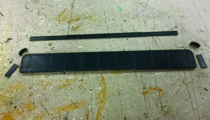
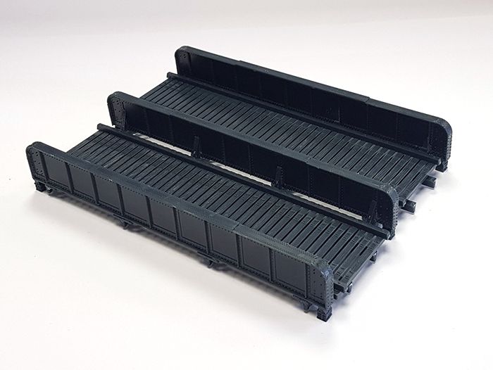
WH933-2948 caught my eye and much like the Peco girders, no bridge abutments are provided which means that I can easily adapt the deck section to fit into the brick arches that will carry my line. This bridge can be built for either single or double track as well, and, importantly, has a central girder between the two tracks. The outer girders are a main slab section, with small sections that glue around the outside.
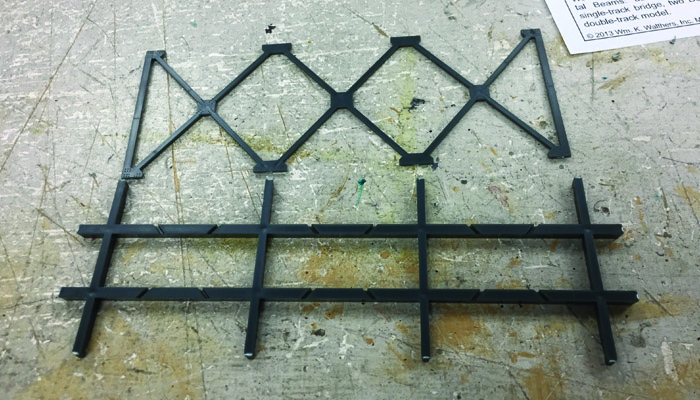
We need three of these in total, two outer ones and the central one. With the glue on these drying, here I used the Revell Professional Glue, we move on to the underside lattice of the bridge. This comprises the main metal frame, and the angled lattice itself; there are slots in the main frame that the lattice slots into.
With both of these done, we can sit them together and add the central girder.
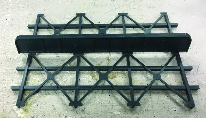
Next, we add small strengtheners to support the central girder, four each side of the girder where it meets the frame.
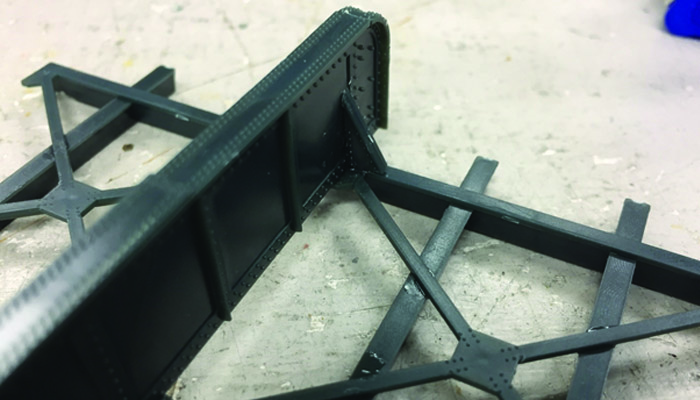
At this point, I decided that I would not add the strengtheners to the outer girders, so that I have more flexibility in the track spacing. TRACK SPACING! I realised at this point that the manufacturers tend to be shy when it comes to this aspect of the dimensions, overall size is often given but not the distance between the track centres. Our shop layout has a level crossing made from the Peco level crossing bases, so this is at the standard UK Setrack geometry. Sitting the bridge on this with one side aligned with one track, we can see that it is narrower:
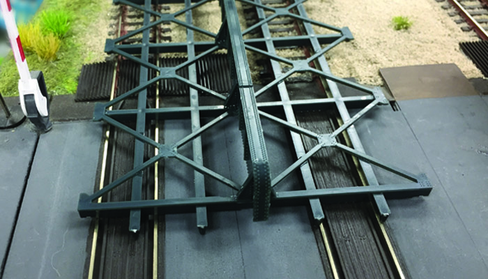
This looked suspiciously like the Streamline track spacing. Grabbing a couple of small radius points and sitting them back-to-back as a crossover shows that it is almost exactly this.
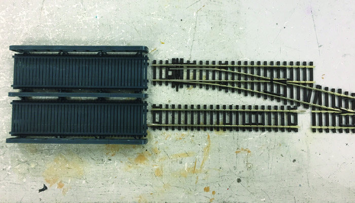
This was an unexpected bonus! If you are using Setrack then this could be made as two single track bridges set side by side. Many bridges in London have a double track bridge as the centre, and two single spans added either side when the line capacity was increased to four tracks. It is also very common where the outer two tracks of a four-track line have slewed away from the centre two to accommodate upcoming platforms.
The completed bridge deck has little feet that glue to the ends of the girder sections.
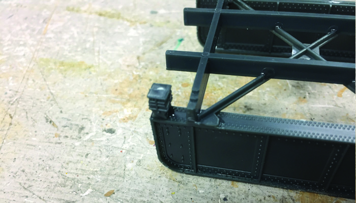
These could be omitted depending on the thickness of the baseboard in the approach to the bridge, and how exactly you choose to mount the bridge onto the abutments.
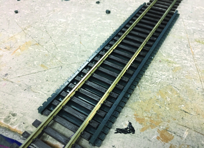
Moving on to the top of the deck, there are a couple of options for how the track is mounted – the top of the deck section has moulded rail chairs, if you want to strip the sleepers from a section of track where it crosses the deck you could simply attach the rails directly.
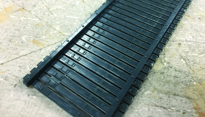
The alternative is to lay the track directly into the trough, Peco track is a perfect fit.
Our bridge is now basically complete. Once it is placed onto the layout, final detailing and ballasting can be done. I can see a home for at least two of these on my layout; there is enough flexibility in construction that it will be useful in many places, and at many angles with girders offset to match the angle of the road below.
Overall, this is a very simple but effective kit that I am very pleased with and took no time at all to build!