

 MARTIN LOVELL looks at how you can apply different types of switches on your model railway.
There are many different types of switches and to some people strange descriptions such as DPDT can be confusing. In this article I will try and explain the various meanings and provide examples of which switch can be used for certain applications.
The letters describing the switch action are as follows:
Therefore, a DPDT switch is ‘Double Pole Double Throw, meaning a switch with 2 contacts which can move in 2 directions, sometimes with a Centre Off.
So, to the various types of switch and their uses.
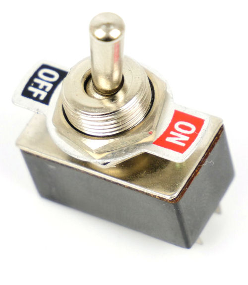
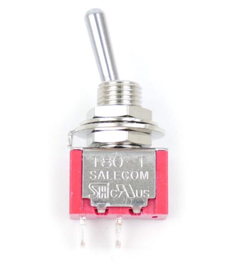
A GM503, or a GM507 Mini, Single Pole Single Throw switch (SPST) is a simple on/off switch, turning lights on, or powering an isolated section of track and so on.
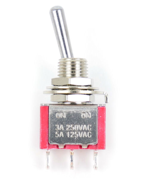
A GM509 Centre Off Mini, or a GM508 Mini, Single Pole Double Throw (SPDT) can be used for switching a 2-aspect signal.
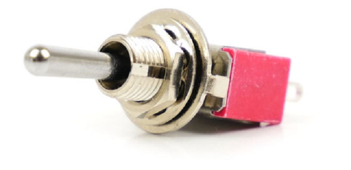
For operating solenoid point motors the GM510 SPDT (Momentary) Mini-Toggle Point Motor Switch is used. This is a SPDT switch but is non-latching, which means that the switch does not stay in one of the “ON” positions but returns to the “OFF” position when released. A word of warning, if the GM508 or GM509 switch is used for solenoid motors the point motor is liable to burn out.
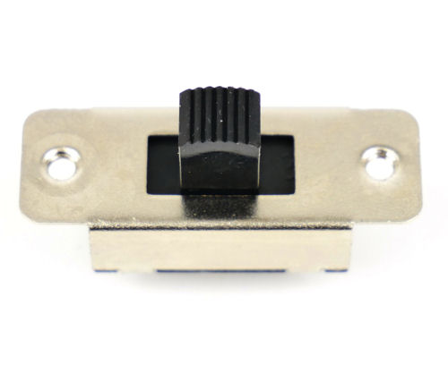
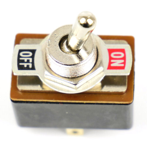
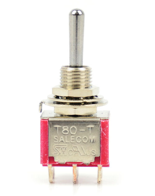
A GM502 Centre Off Slide, or a GM504 Toggle, or a GM505 Centre Off Mini, or a GM506 Mini, Double Pole Double Throw switch (DPDT) is most useful, it can be used for switching between 2 controllers, polarity reversal to operate LED type signalling, changing the polarity of a live frog point if an accessory switch is not fitted to a point motor, and so on.
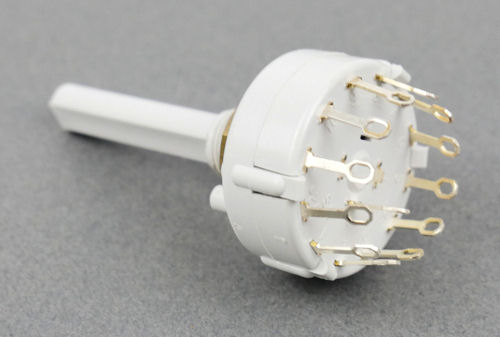
Another type of switch is the Rotary switch, this has a rotating set of contacts, which contact specific outputs when the switch is turned to the required position.
The description of these is as follows:
1 pole 12 way (GM519) 1 input with access to 12 outputs – which could be used in a fiddle yard application to make an isolated section live, for example.
2 pole 6 way (GM520) 2 inputs to 6 outputs - which could be used to make lines off of a turntable live if power is not automatically switched to the roads by the turntable, such as on the Atlas table.
3 pole 4 way (GM521) 3 inputs to 4 outputs – this is ideal for switching 3 aspect colour light signals.
4 pole 3 way (GM522) 4 inputs to 3 outputs - it can also be used for signals, especially 4 aspect colour light.
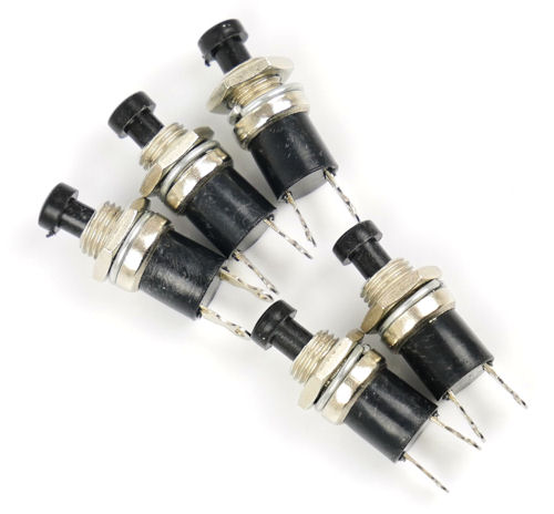
Miniature push switches (GM513 to GM518) can also be used to operate points - with one for the left and one for straight on - as these are non-latching.
The best way to organise your switches would be on a control panel, preferably with a track diagram with the switches placed on the point or signal or section which they are controlling, rather than just in a straight line which might cause confusion or mis-operation.
With all the wire connections running from the switches to their destinations, it is essential that the wires are kept tidy for ease of maintenance or for tracking faults. It is a good idea when planning your layout to decide on a colour code for track power, point motors signals and the like, to make tracking easier in the event of a fault.
Keeping the wires under the board tidy, i.e. not dangling down and liable to be caught, is made easier with the likes of cable clips, keeping them all together.
I hope this article has been helpful in removing some of the mysteries behind switching,
Happy modelling.