
 JAMES HICKMAN looks at wiring and how his layout Ledworth could be wired.
So far in this series, we have looked at Planning The Layout, and Fiddle Yards, constructed the Baseboard, and laid the track. What's next? Well wiring of course. Wiring a layout can be a bit of a daunting task, and we regularly hear the phrase 'Well, I'm no electrician', but you don't need to be.
In basic terms, there are two ways of wiring a layout. That is for analogue control, and for digital control. The choice is yours complete when it comes to this, some people and layouts suite the more traditional operating style while others require or prefer DCC. For example; my own OO9 layout 'Hope Springs' is a simple analogue shuttle, whereas my other layout under construction, as yet unnamed, is fully DCC operated. I could talk all day about the pros and cons of each, but ultimately it is down to a lot of personal decisions and factors that are unique to the individual. So with that in mind, I will be talking through the wiring of 'Ledworth' for both scenarios.
I am not favouring either analogue or digital in this article as I do not want to influence your choice with that, and am simply starting with Analogue as it was around first. There are a few common misconceptions when it comes to wiring, and that is that analogue wiring is simple, and DCC is complicated. That is simply not true, as with both styles of control, you can make the wiring as complicated or as simple as you require.
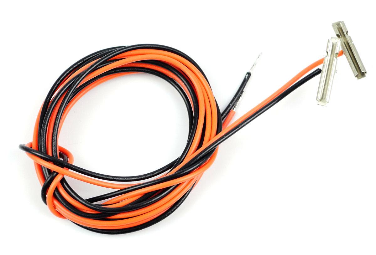
The GM13 version of the powered joiner.
In the previous article about laying the track, I mentioned that if you preferred using wired fish plates on your layout, that is was best to drill the holes for these and feed the wires through at that stage. If you don't or would prefer not to use them, there are other methods of connecting wires to your track too.
For a good many years, and quite possible for more than my time on this earth, Hornby have produced the good old fashioned power clip. This clip simply pushes under the set track of their track range and delivers power for whichever controller you desire. Although these are very often found on a layout, they can become weak through multiple ins-and-outs under the sleepers through the years, and thus Hornby have also produced a power track for a stronger connection. Peco do separate power clips for both N And OO Scale, and there are other clips and connection methods available on the market too.
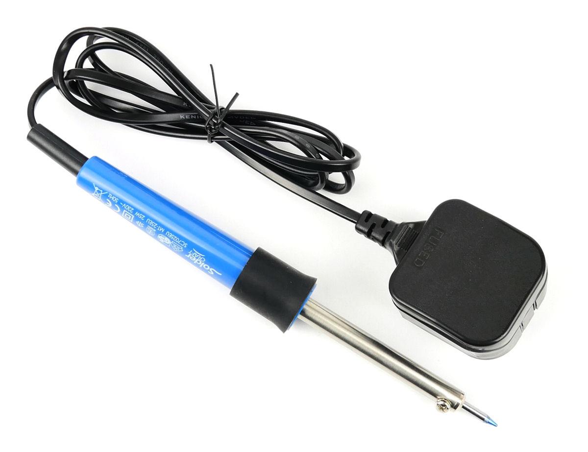
A traditional soldering iron.
The downsides of all of those above is twofold. The first being that no matter how good the connection is, there is no permanent connection, and over time, through use, these connections can become weaker. The second is that they rely on something being plugged into the track. This is fine when you are starting out, but if you are wanting to create a realistic scene, a large power clip is going to be very difficult to disguise. So, what is the solution? As previously mentioned; track feeder wires are a brilliant solution, and they take the place of a regular rail joiner. They then allow you to drop the wires strait through the board and out of site. The downside of these is that they are limited to the number of track systems you can use them with, and they need to be installed as the track is laid.
The ultimate connection is a soldered connection. This is another thing that is considered a dark art buy some, but it need not be. There are many good videos out there showing soldering basics, but the best tips I have for you are to use a hot soldering iron, and apply heat for the least time possible. A hotter iron used for a few seconds is better than a cooler one used for a few minutes. This means the quick burst of heat will not melt your sleepers, but a slow cooler heat will. The other tip is to keep your tips clean. Keep using an appropriate sponge to periodically clean the tip of excess solder and flux, and never file your tips down as this will allow any flux to start attacking the tip.
If in doubt, take a spare bit of track, less than a metre will do, and solder some short lengths of wire every couple of centimetres along its length. The connections won't be great at first, but by the end you should be soldering good quality joints and you'll be ready to attempt the real thing.
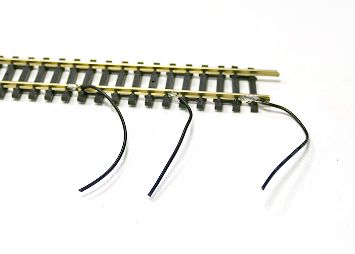
A practice rail. You can see that these are not perfect connections, with each displaying a different trait. Th first has solder on the top of the rail, the second has loose wires not attached, and the third has melted the sleeper.
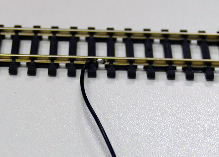
The ideal joint, as seen here, is not covered in to much solder and stays away from the top of the rail too.
With analogue, you need to consider where your feeds will go. From the diagram below, you will see that the positions of the feeds for Ledworth. Some of you may have noticed that there is no feed coming in for the top line at the right. This is intentional as the layout will be operated prototypically, in the sense that when the upcoming point is against the train, it will not be able to enter the station, for obvious reasons, and thus there is no power needed. When the point is clear, the catch point at the top left of the diagram would also be set streight, and the power is supplied form here. Prototypically this scenario is used to stop the trains failing to stop and trespassing onto the other line, but also creates some rudimentary interlocking in this case. Both catch points and interlocking are very big subjects in their own right, so for anyone interested some further reading maybe advised.
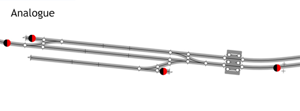
Analogue feed locations for Ledworth
The other feeds on the layout operate it in the same or similar way, controlling the flow of power depending on the position of the points. This layout is using insulfrogs, the differences of these compared to electrofrogs and unifrogs would also be of beneficial research to those not knowing, means that I do not need isolated sections as the points do the isolating. For other types of points isolated sections or joints maybe required.
Because the layout is a terminus with run round, I will only ever be running one train in the area at a time. Others maybe present, but only one will be operating. Because of this, the layout is only needing one analogue controller. The lowest feed on the siding would be wired with a switch, so only allows a stored train to move if either the point is thrown or the switch is activated. All the other feeds would be a constant live. This layout would only be wired using a supply of GM11 wire in various colours as that is all that is needed and no 'high rated' wire is required. The wires would be connected using terminal blocks or soldered and the joints protected with heat shrink.
DCC wiring is simpler when it comes to feeds for this layout. With DCC you only really need to remember that every section is powered., As long as you are not using a train detection system, then the below would be the perfect position of feeds. This allows full power to flow all over the layout at any one time, even allowing stationary locomotives to keep their lights and sounds running if these are present.
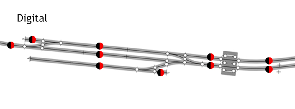
Digital feed locations for Ledworth
The other reason that you power every part is so that you can control every part. Regardless of where a locomotive is on the track , with DCC you would wish to be able to control it, so powering everywhere is essential.
And that's it, a layout like this does not need anything to specialist for wiring, but others may, regardless of their control method. A reverse loop is something that appears on a lot of layouts and this would need additional wiring either way, we have articles in our archive outlining how to do this along with a host of other articles to help, so check out the electrics section for further help.
And that brings us to the end of the wiring for the layout. The next stage of the layout is the point motors. This will be the final part of this 'getting started' series sadly as from then on it is onto the ballasting and scenic work, and that's where the real fun begins.