
How To Install Tortoise and SMAIL Slow Action Point Motors

The Tortoise And The SMAIL
The Tortoise range of point motors from Circuitron is perhaps the best-known and most trusted range of slow-action point motors, and the basics of the design date back to the mid-eighties. Here, we take a look at the main differences compared to conventional solenoid motors, and what you need to use them.

There are two types: the original Tortoise, which can be considered the “analogue” version, and the Slow Motion Actuator with Integrated Logic motor or SMAIL for short, which is the newer “DCC fitted” variant with a built-in decoder. The most common power supply for the Tortoise is a 12-volt DC unit, not the 16-volt AC commonly used to power solenoid motors. While solenoids use a pulsed power supply to the motor's coils, slow-action models like the Tortoise use a 2-wire DC system, in which the motor is controlled by reversing the polarity of the supplied power.

Connecting the Tortoise and SMAIL Motors
The Tortoise has an 8-pin connector protruding from the casing – for those happy to solder, the pads at the edge of the connector can be soldered to. The motor itself takes power from the two outer connections, and the remaining six are split between two separate single-pole switches. These switches can be used to control things like frog polarity on the points themselves, or to feed back to a mimic panel to operate indicator LEDs. For those less confident in soldering, the range also includes 8-pin connectors that easily push onto the circuit board; these replace solder pads with screw terminals, allowing wires to be attached without soldering.
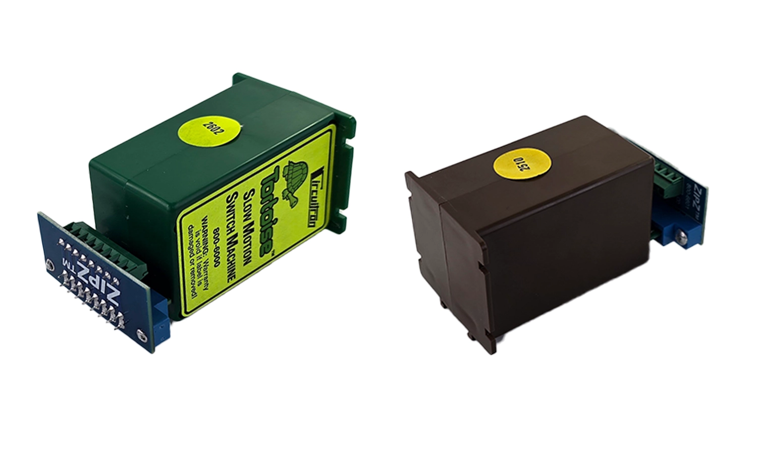
The ZipZ connectors fit both the Tortoise Motor and SMAIL Motors
The digital SMAIL version can also be bought with just the circuit board option for those happy with soldering, or with the connector already applied. Connections to this motor are again the two outer connectors; rather than attaching to a power supply, connect them back to your chosen digital system. This could be by connecting directly to the rails, to a bus bar, or running directly to the back of your controller. We recommend that, when installing any digital accessory, a separate bus be run to make future fault-finding easier if issues arise.
How to Prepare Tortoise and SMAIL Motors for Installation
When it comes to either the Tortoise or SMAIL motors, very little is needed to install them. All you really need is a decent-sized crosshead screwdriver, strong cutters to trim the throw wire, and a pair of flat-nosed pliers. If you plan to solder, then you will, of course, need equipment for that too.

So, let’s see what we get in the box. Along with the motor itself, each Tortoise and SMAIL is supplied with a small packet containing the throw wire and a screw to hold it in place, and a fulcrum. This can be moved up and down to vary the amount of throw for the motor, so it can be used with small scales such as N Scale or the smaller Narrow Gauges that need minimal throw, but can also be mounted to allow for bigger scales, such as O Scale, where the point blades have further to travel. Of course, it is also ideal for the scales in between, such as OO Scale and HO Scale.
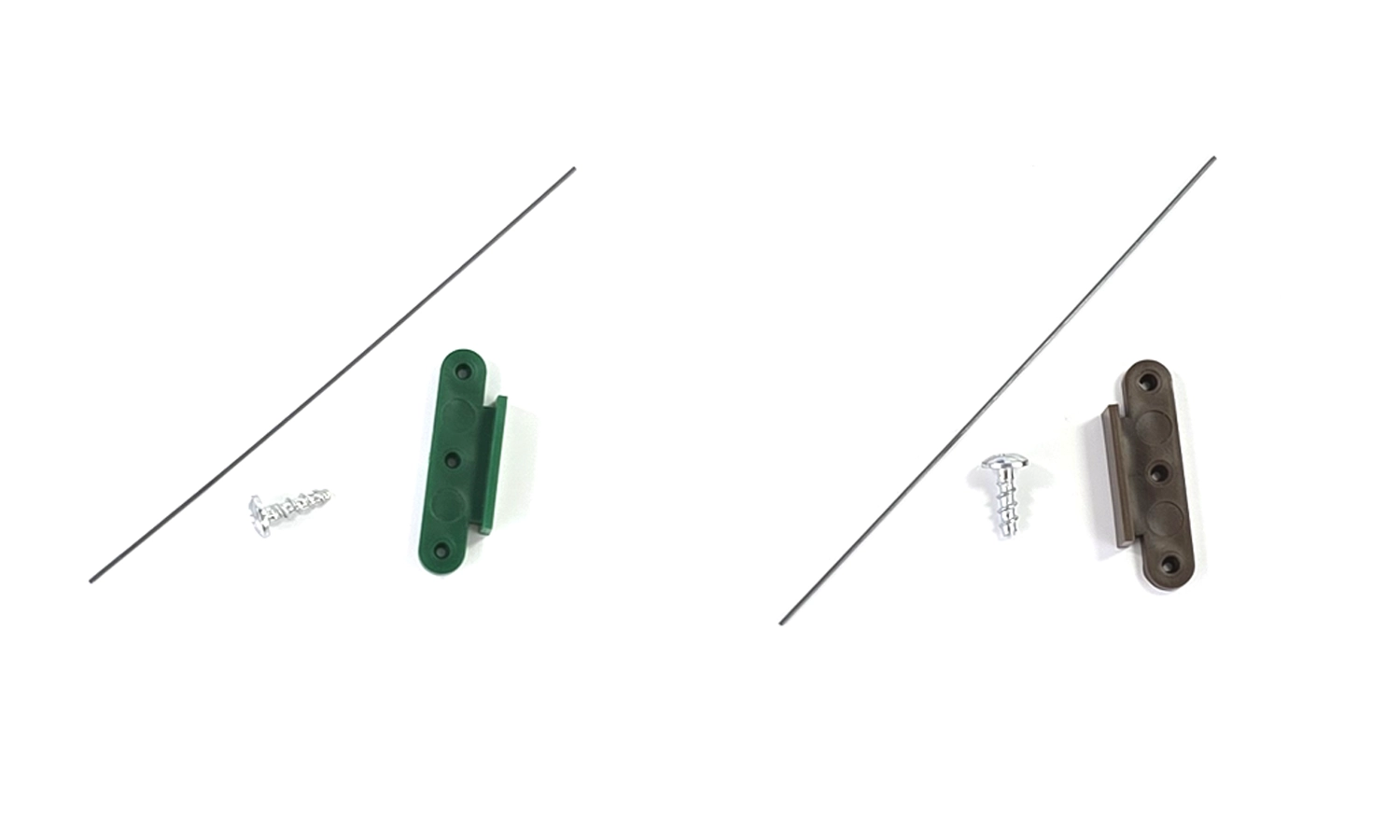
Components for the Tortoise and SMAIL Motors can be identified by the colours. Green is for Tortoise Motors, whereas Brown is for SMAIL Motors.
When installing the throw wire, it is best to use a pair of pliers to bend the wire to match the shape on the right-hand side of the instructions – it doesn’t have to be perfect! Then the fulcrum can be installed, simply sliding in. The default position for this is at the top of the motor. If you find the throw isn’t strong enough, it can be adjusted later
The small hook end of the wire, created when it was bent, can now be pushed into the small hole on the black actuator, and the screw is then installed to hold it in place. Be careful when doing this; don’t push too hard on the actuator. The wire will be under very little force here, so it doesn’t need to be screwed in too heavily. Applying too much pressure can damage the gearing.
How to Connect and Install a Tortoise Motor.
In the following stages, we have opted to demonstrate the process using a Tortoise motor without the screw terminals attached. This is the original motor in its basic state to highlight how easy it can be, and soldering the connections offers the most reliable long-term connection. If you do not want to solder, this is the stage to connect the solderless terminals and insert the wires at the same points they are being soldered in this example.
For ease of installation, short wires are being soldered to the power tabs and connected to a terminal block – this is much easier than soldering upside down and makes it easier to remove the motor again if required. First, the wires have had their ends stripped and tinned with a soldering iron, then passed through the terminal holes from the back. Using the pliers, gently squash the tinned wire against the terminal pad – it will be easier to solder if the wire is already in the right place!
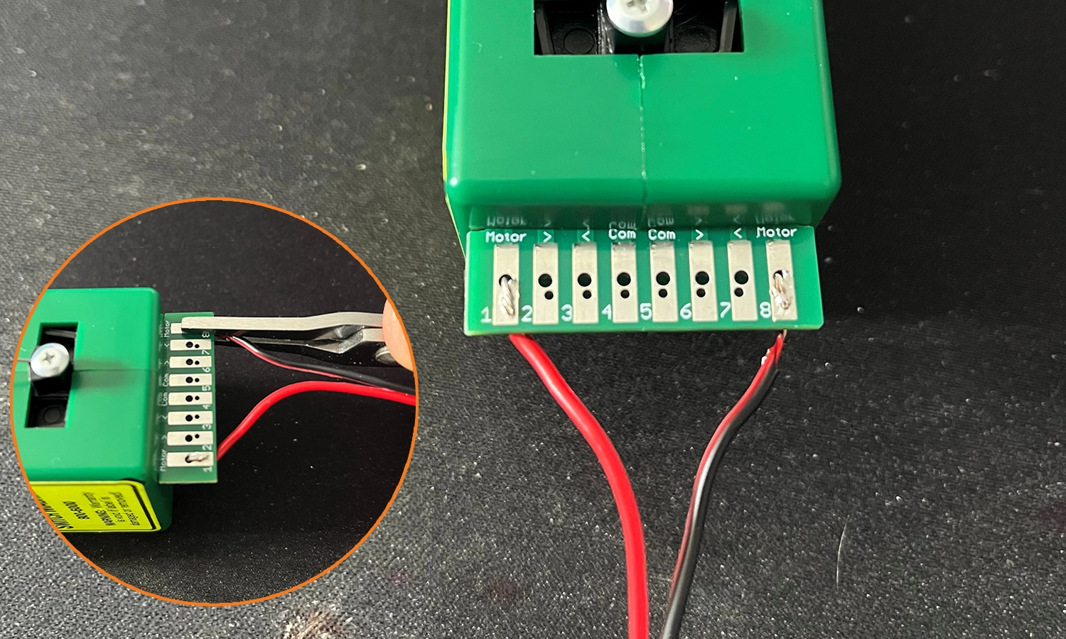
With these wires connected, it is time for a quick test – as this is 12 volts DC, a Gaugemaster Combi controller can be used as a power supply to test the motors, as it has the added benefit of having a polarity switch to reverse the polarity. With the wires connected to the Combi's track output and the switch in the central neutral "Off" position, the voltage can be turned up. Changing the direction switch will reverse the motor. When the motor is fitted in its final location, a Wall Mounted Transformer is recommended. The Tortoise motors draw very little current, and this transformer would be ample for a good 60 to 80 of them being activated at the same time. As most layouts are not operating more than one or two points simultaneously, only one transformer would be required for all the Tortoise motors on a layout.
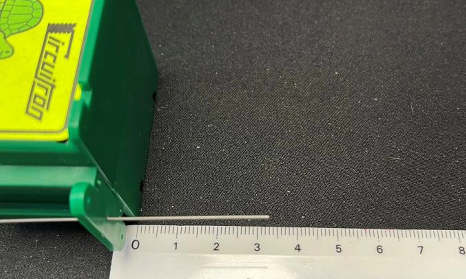
When it comes to mounting the motors, they are designed to be installed under the baseboard. The supplied throw wire is long enough for baseboards up to 1 in (25mm) thick.
These are surprisingly easy to mount – unlike the clip-on solenoid-style motors, these slow-action motors don’t need a huge rectangular hole, just one big enough for the throw wire to fit through across the range of travel – half an inch or 10 to 12mm will be enough to accommodate the throw arm for most scales. With this hole drilled, use the template provided to drill pilot holes for the mounting screws. The motor can now be installed by passing the throw wire up through the hole and the hole in the point's tiebar. Many modern points come fitted with a centring spring that is designed to hold the blade in place when operated by a solenoid motor or by hand. As the Tortoise and SMAIL motors utilise a fulcrum that holds the throw wire in place, this centre spring is best removed. This will reduce the tension on the motor and result in a more realistic throwing action of the point.
Once the holes are marked, the motor can be fixed in place using the four screw holes. There is enough flexibility in the throw wire that we don’t need to be 100% accurate with alignment; you don’t exactly need to measure angles here!
Last of all, we need to cut any excess throw wire away – Don’t be tempted to use track cutters for this, as they will break and you risk injury! Whilst the wire is very flexible, it is also very tough. Using either a cutting disc or something similar mounted in a rotary tool, if you try to use an enormous shear-style cutter, it can be very awkward to get a decent cut in close proximity to the track, which in turn risks damaging point blades. In any case, whichever method you use, wear eye protection!
Once the motor is fitted, the fulcrum can be positioned to allow the throw wire to travel exactly the desired distance.
Operating a Tortoise Motor
As the Tortoise Motors use a 2-wire power system and not the 3-wire system found on solenoids, a different style of switch is required. There are several options, such as Slide Switches or Toggle Switches; we will cover the most common here.
Double Pole Double Throw (DPDT) Switches
When using the aforementioned Wall-Mounted Transformer, we can use Double-Pole Double-Throw switches. In this instance, a Slide Switch is used; however, a Toggle Switch wires up in the same way.
A DPDT switch has 6 terminals, and as the switch is operated, it will connect one end pair with the centre, and when reversed, the other end pair with the centre. By feeding the 12-volt power into one end pair of terminals and then swapping the wires when connecting to the other end, a polarity-reversing switch is created, which reverses the direction of the operating motor.
The diagram below shows how the power will flow through switches set in different positions. The left-side switch is in the “up” position, and the top and middle terminals are connected. On the right-hand side, the switch is in the “down” position, so this time the bottom and middle terminals are connected instead. Looking at the current flowing from the switches to the motor, we can see that it is reversed.
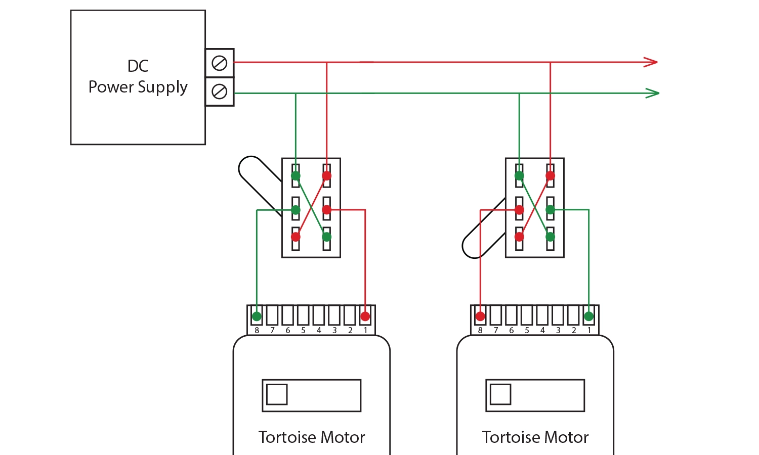
A simple diagram showing how two DPDT switches can be wired to operate two tortoise motors. Note the crossing of the wires in the middle of the switches.
The image below shows the crossed wires fitted to the switch using Push Connectors – the centre terminals that are currently empty will run to terminals one and eight of the Tortoise.
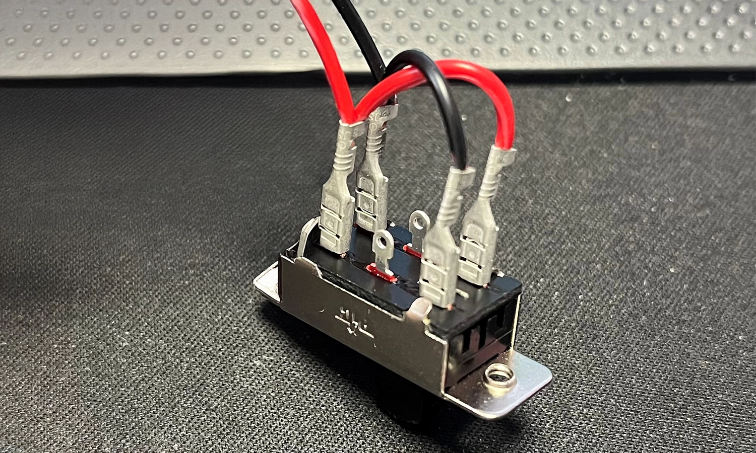
The push connectors crimp onto the wires and push onto the switch.
Once all the connections are made between the motor and the switch as well as the switch to the power supply, a simple throw of the switch will be all it takes to activate the motor, as seen in this short clip below.
How to Connect and Install a SMAIL Motor.
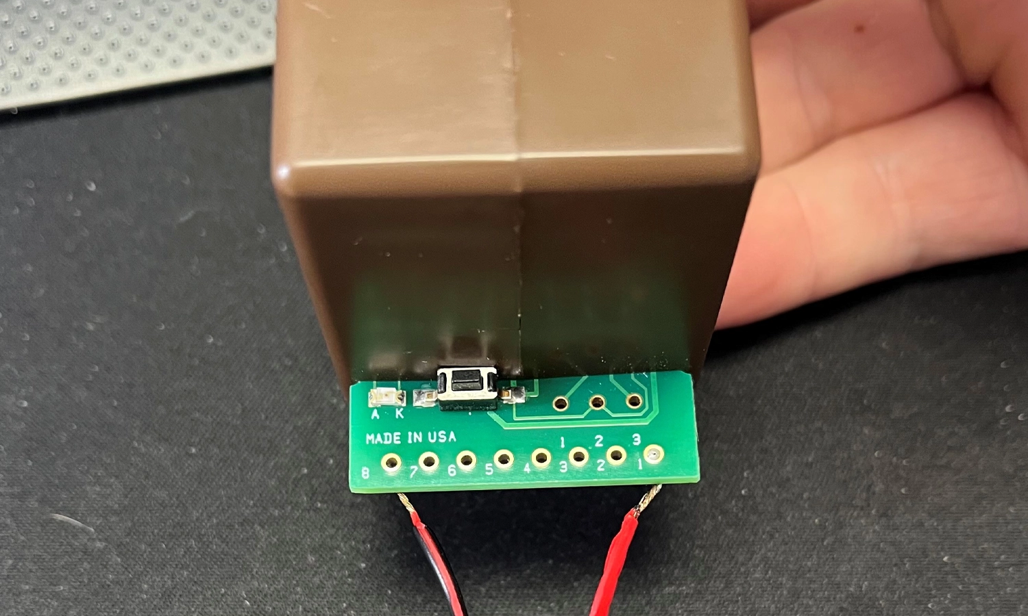
The SMAIL is the DCC-fitted version of the motor – these are visually almost identical to the Tortoise, but with a brown casing. As with the Tortoise, a connector sticks out of the housing; at first glance, this would appear the same, but it does actually have extra connections – these can be used to control the motor using push buttons, or even detector systems to change them. There is also a small button located here for programming, which will enable the motor to be set up during the installation process.
If we take a look at the wiring diagram, it can be a little confusing at first - the wires showing the DCC power connection exit the diagram at the top, marked by arrows. Looking at the switches shown on the diagram, these also exit the diagram to the right, circled in red below - but what power supply do they connect to?
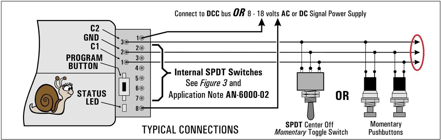
The simple answer is that no separate supply is needed. The SMAIL itself supplies power for any operating switches you decide to use. The arrows on the diagram above show that extra switches can be connected, including reed switches and OPTO sensors. This means you can use both a manual switch and a sensor to throw the point.
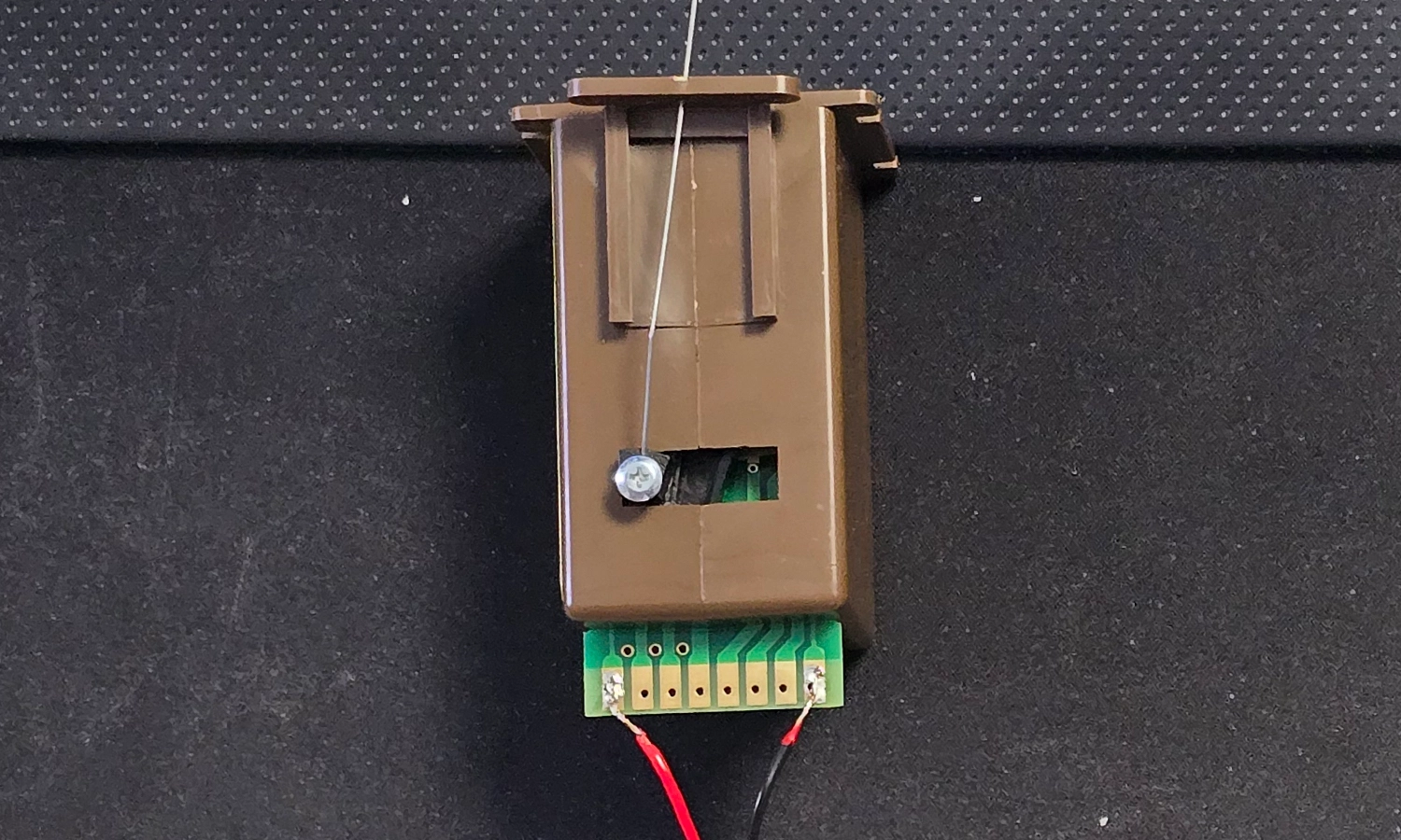
Wires have been soldered to the power input terminals of the SMAIL motor.
Looking at the motor above, power wires have been soldered on, as with the Tortoise, to terminals one and eight. Terminals two, three and four, plus terminals five, six and seven, work as single-pole double-throw switches. These are ideal for frog polarity and panel indication lights. Above those terminals are the extra three connections: Ground, Common One and Common Two.
Flipping the motor over, the status LED becomes visible, the learn button, and the 3 extra terminals. To test the motor prior to fitting or programming, DC or DCC power needs to be applied to terminals one and eight as before. However, the SMAIL will not operate by reversing DC polarity. What needs to be done here instead is to bridge the ground terminal to either C1 or C2 – this is exactly how a push-button switch would work.
An easier option for testing is to test it on a DCC supply - after all, this is the DCC Fitted variant. First, the motor needs to be assigned an address, which would be required to operate from a digital system regardless. This is a simple process; no CV programming is required as the SMAIL has a “learn” button. Much like those found on many of the Train-Tech range of products.
How to Program a SMAIL Slow Action Point Motor.
- Connect to DCC power, main track.
- Press the “learn” button.
- Operate the accessory number that we want the decoder to be.
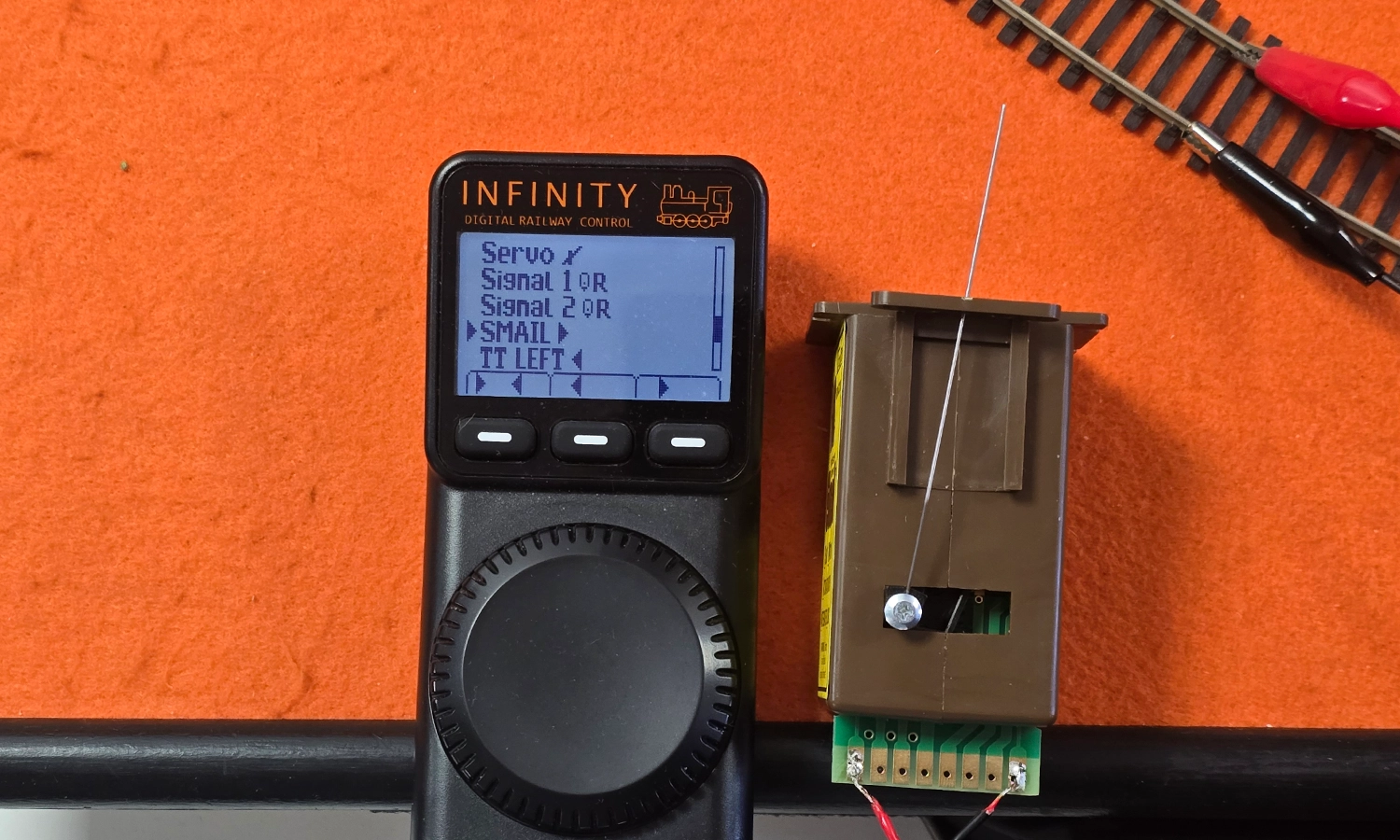
In this example, "Jump Leads" are being used to temporarily connect power to the motor. These have been made from a pair of Crocodile Clips and some red and black wire, such as the Gaugemaster Twinned Wire.
Now press the learn button
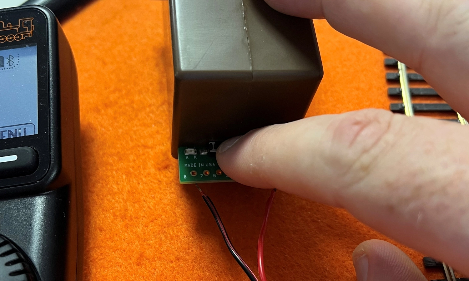
A quick press of the button switches the SMAIL into "Learn Mode".
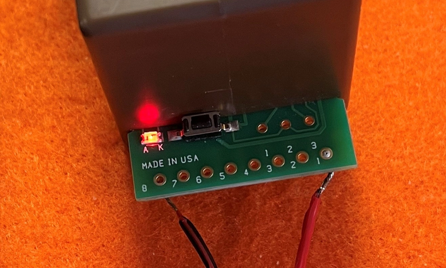
When the LED is illuminated, the SMAIL is in "Learn Mode".
The LED shows that the motor is "listening" for an activation address. Select the accessory on your digital system; in this example, the Gaugemaster Infinity Digital system is used, and activate the accessory. Once you have operated the accessory, the motor will move the throw arm to confirm, and the LED will extinguish, as seen in the video below. Programming is now done!
Easy peasy!. Now that the motors have been tested, they can be installed in their final location. As the SMAIL is physically identical to the Tortoise, this is done in exactly the same way as above.
This covers the basics of both models; there is plenty more that both are capable of, and this is covered in the main instructions, especially when connected with other components from the Circuitron range.